
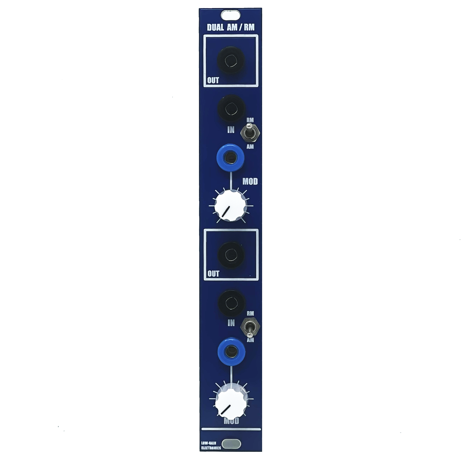


Dual AM/RM
DESCRIPTIONTwo high quality balanced modulators capable of Amplitude Modulation or Ring Modulation.
DETAILSDIY PCB / Assembled Module
Current: TBD
PCB Size: 6” x 1”
The AD633 is one of my favorite IC’s available to this date! The AD633 is a 4 quandrant multiplier chip that requires next to no external parts to make it work! It can be used as ring modulator or an amplitude modulator. But the beauty about this chip is when your modulator signal goes negative it actually inverts the output signal’s phase. So it becomes a thru zero(“TZ”) VCA.. or a VC Bipolar attenuator. Lots of fun can be had with this function block! And every system should really have at least 1!!! if not a bank of 8 of them!
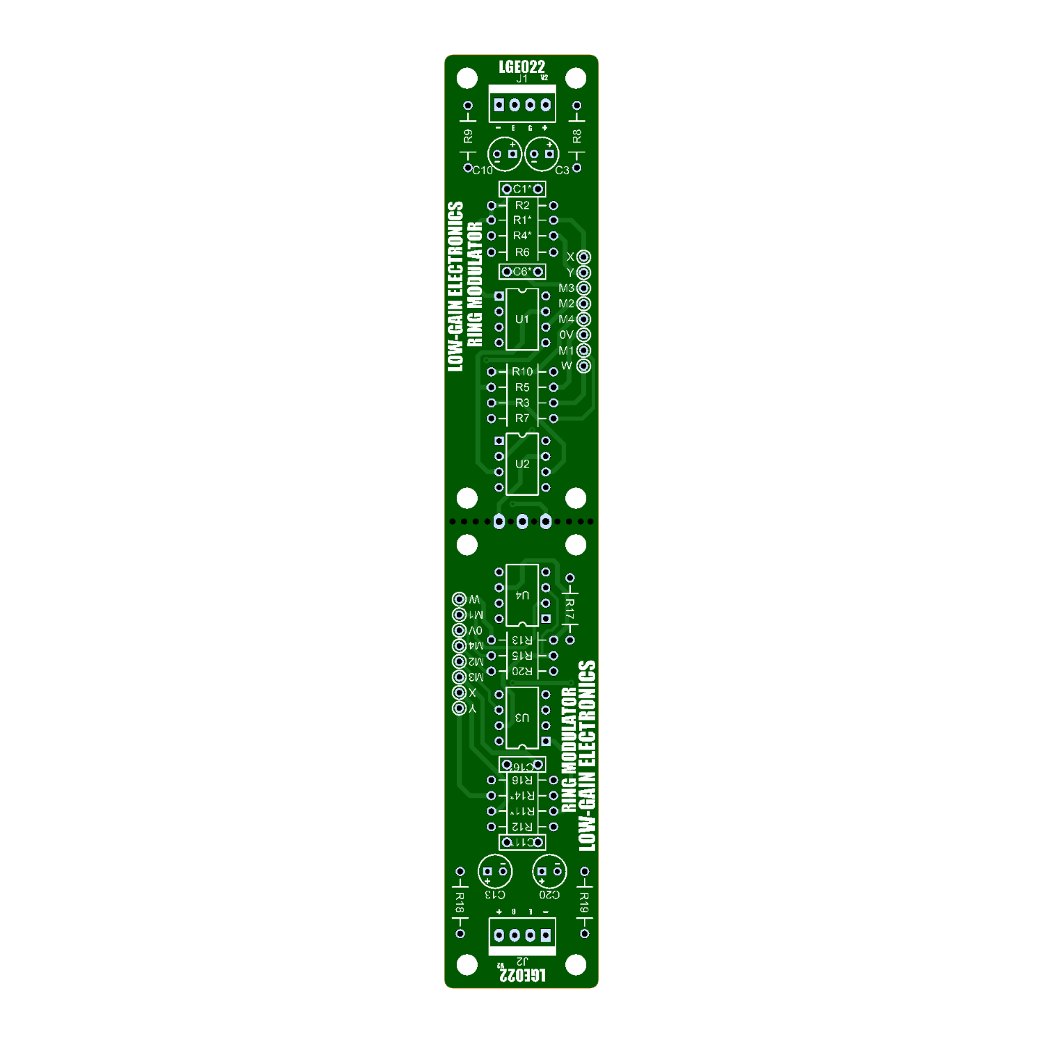
Version 1 of the LGE022 PCB was mostly designed as a pcb to install between modules on a system panel. To add a simple 3 jack Ring Mod / TZ/BiPolar VCA. When I got more into the circuit a bit and saw how Ray Wilson had implemented a dedicated AM mode I was inspired to expand on the pcb a bit. It now has dedicated AM and RM modes. I tweaked his concept a little to allow for equal output signals between modes and removed the coupling caps to make the module be DC coupled for CV applications. I cannot recommend Ray Wilson’s website and book enough if you’re looking to learn more about modular synth circuit design and understanding! The main PCB was designed to be easily snapped in half should you need to fit just one into a smaller space or behind a panel, etc. That said, the power header, 10uF caps, 100n caps and 10R resistors on the power input section is not needed on both sides if you’re building it as a Dual AM/RM. This board could also be used in conjunction w/ an existing module as CV input processors allowing you to “modulate the modulator” w/ VC Bi-Polar Attenuation!
This project has so few parts it makes for a great first time builder project! The AD633’s aren’t cheap but they simplify the assembly and sound amazing!
Version 2 DIY Build Information:
LGE022 V2 Main Board Bill of Materials
LGE022 V2 Main Board Schematic
LGE022 V2 Main Board Designator Layout
LGE022C V2 I/O Board Bill of Materials
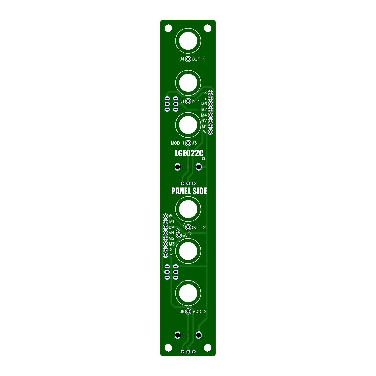
LGE022C V2 I/O Board Schematic (Wiring Diagram)
LGE022C V2 I/O Board Designator Layout
Version 1 DIY Build Info:
LGE022 V1 Main Board Bill of Materials
LGE022 V1 Main Board Designator Layout
LGE022 V1 Main Board Schematic
LGE022C V1 I/O Board Wiring Schematic
Mechanical Parts BOM generally required for building Low-Gain Electronics Modules
Details:
PCB Size: 6” x 1”
Current Draw: TBD
** 4U Modular is a term used for the format most commonly known as “Serge Format” or “Loudest Warning Format”. Out of respect for the ever growing format, 4U Modular is the easiest way to refer to it. More Specifically it refers to the panel height and mounting hole style. 4U Modular will patch up just fine with other 4U "Serge" formats such as "Random Source", but it will not mount in RS boats or Buchla Boats (or power off Buchla power for that matter). An info page about this will be added to the website soon to make this a lot more easy to understand.