


VC Filter/Oscillator
A classic 2-pole pingable filter based around a classic 70’s 4U Modular OTA Filter design. HP, LP and BP outputs. 12dB/oct LP & HP, 6dB slopes on the BP. While this filter doesn’t oscillate w/o resistor changes and buffering, it is ping-able and capable of producing beautifully rich tones.
State Variable Filter based around a classic 70’s 4U Modular OTA (CA3080) Filter design. HP, LP and BP outputs. 12dB/oct LP & HP, 6dB slopes on the BP.
UPDATES 09/26/2023
R26 = 34k (Removes initial resonance from open filter settings.
1N4733A 5V1 Zeners installed for Resonance stability / clamping modification.
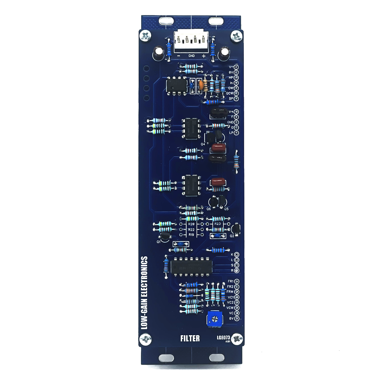
Filter PCB (v1.0) Build Info:
LGE073 v1.1 Bill of Materials
LGE073 v1.1 Schematic
LGE073 v1.1 Schematic Resonance Stability/Clamp Modification
LGE073 v1.1 PCB w/ Designators Resonance Stability / Clamp Modification
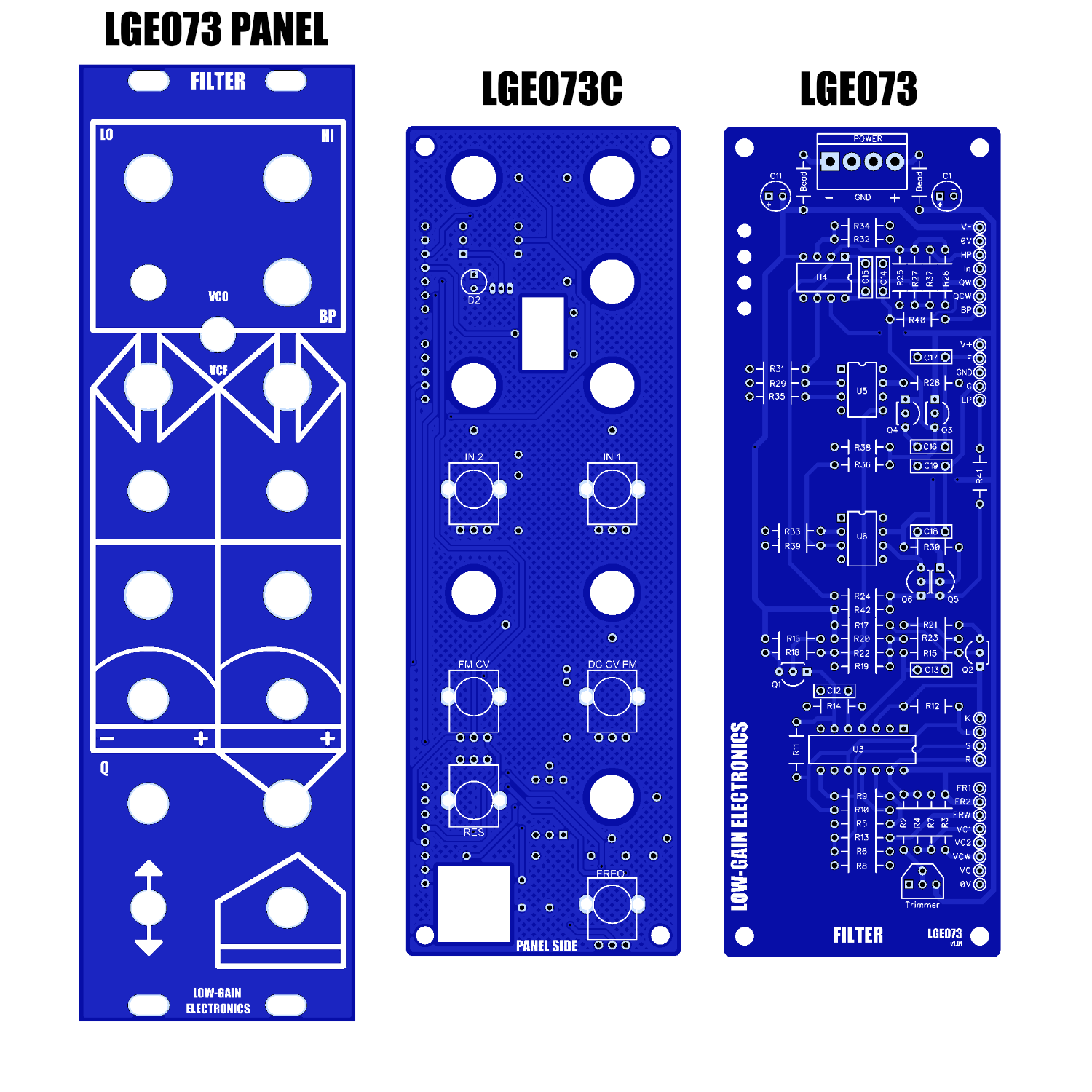
LGE073 v1.1 PCB w/ Designators
LGE073C v1.2 (Currently what ships)
LGE073C v1.2 I/O PCB Bill of Materials
LGE073C v1.2 I/O PCB Schematic
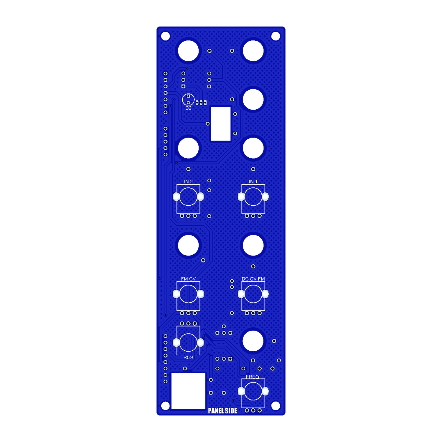
LGE073C v1.2 I/O PCB w/ Designators
LGE073C v1.0 (Old Rev, minor changes)
LGE073C I/O PCB SCHEMATIC (WIRING DIAGRAM)
LGE073C v1.0 I/O PCB BOM
LGE073 & LGE073C v1.0 board wiring
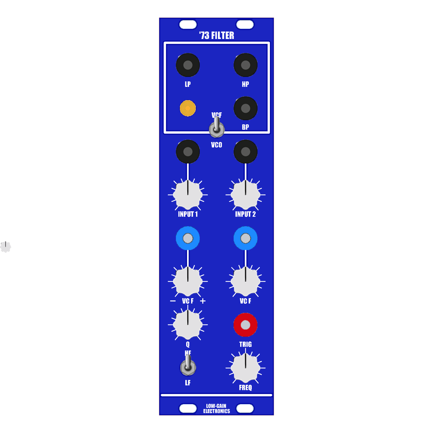
Paperface Artwork
Quad Buffer PCB Build Info:
Bill of Materials
Schematic
PCB Designators
Mechanical Parts BOM generally required for building Low-Gain Electronics Modules
CA3080’s can be purchased new from places like Thonk, Synthcube & Modular Addict. They are made by Rochester Electronics and Alfa (AS3080)
Build notes and Modification:
The bias for the LM/CA3080 OTAs can be omitted if you don't have any 22M resistors. The associated 100k and 15k could also be omitted if you omit the 22M resistors.
If you wish the filter to self oscillate at high Q settings, R26 (68k) between pins 2 and 6 of the single op-amp (TL071 / LM748) can be reduced to 27k. Doing this will drop the output levels significantly. To recover the levels, feed the LP, BP and HP outputs through three of the optional buffers on LGE100 Quad Buffer PCB (sold separately), with 39k resistors used in positions marked RGx.
A TL071 can be substituted for LM748. If TL071 is used, leave out C4 (5pF) capacitor.
The resistors marked RGx on the LGE100 Quad Buffer PCB are for setting the gains of the optional buffers. Typically 39K will get you in the
ball park for resonance modification.B25-100K linear pots can be used.
Possible use for LGE1000 Quad Buffers PCB include buffering the input and CV input to compensate for their lower-than-usual input impedance, or buffering the outputs after they have been fed though a level pot. This was a common modification in original builds from the 70’s.
A DPDT switch can be added to short points F and G to 0V (GND). Doing this will switch the filter into low-frequency mode allowing for filtering of CV signals. If you don’t add this switch it’s not a big deal.
An Oscillator mode switch can be installed by wiring the common point of the SPDT Toggle Switch to the Input on the PCB. A wire from the BP output jack to one side of the switch and the input jack to the other side of the switch. This removes the Audio input on the front of the jack and causes the filter to oscillate.
** 4U Modular is a term used for the format most commonly known as “Serge Format” or “Loudest Warning Format”. Out of respect for the ever growing format, 4U Modular is the easiest way to refer to it. More Specifically it refers to the panel height and mounting hole style. 4U Modular will patch up just fine with other 4U "Serge" formats such as "Random Source", but it will not mount in RS boats or Buchla Boats (or power off Buchla power for that matter). An info page about this will be added to the website soon to make this a lot more easy to understand.
Assembled Modules are built to order, please be patient when ordering. Use the contact page if you have any questions or requirements!
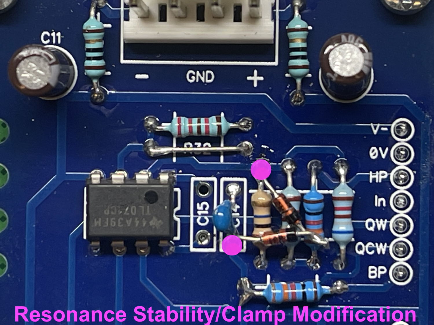
Zener Diode placement on LGE073v1.1

Prism 73 Filter PCB zener placement and resonance fix
(unconfirmed as I don’t own this pcb)

CGS77 PCB zener placement and resonance fix
(unconfirmed as I don’t own this pcb)
Oscillator mode. Toggling the signal input of the pcb between front panel input Jack and the BP output. This allows for the filter to act like a sine wave oscillator. External modulation is applied to the bipolar CV input for cutoff frequency. Minor distortion can be heard from speaker not being able to handle the frequency range of this filter. iPhone 12 camera mic.
Auditioning external signals with slow filter cutoff sweets. External modulation eventually added as well. Minor distortion can be heard from speaker not being able to handle the frequency range of this filter. iPhone 12 camera mic.
Auditioning external signals with fm/audio rate modulation. Minor distortion can be heard from speaker not being able to handle the frequency range of this filter. iPhone 12 camera mic.
External pulse/trigger into audio Input. Cutoff CV audio rate modulation. Dynamic percussive Pinging sounds. Minor distortion can be heard from speaker not being able to handle the frequency range of this filter. iPhone 12 camera mic.