


Wave Multipliers
DESCRIPTIONThe Wave Multiplier affects the timbre via 3 sections of function… Comparator/VCA, Odd-Harmonic Wave Folder, and Drive/Fullwave Rectification.
DETAILSCurrent: TBD
PCB Size: 6” x 2”
Assembled Modules are built to order, please be patient when ordering. Use the contact page if you have any questions or requirements!
“The Wave Multiplier affects the timbre. Unlike the VCF, whose action is a subtractive process of filtering frequencies from the input waveform, the Wave Multipliers are able to dynamically process the input waveform to produce new harmonically-related overtones. This function should not be confused with Ring Modulation, since it is a non-linear process using a single audio input. Although it is possible to describe the effect of a VCF by saying the sound gets “bass-heavy”, makes a “wah-wah” effect, or sounds “thin”, describing the sound of a Wave Multiplier is much more difficult. The input sound comes out richer in harmonics, somewhat similar to pulse-width modulation and to linear frequency modulation, but with a new characteristic timbre. The nearest we can come to describing the unique sound qualities (there are three different sections) is to say that they alter the timbre in exciting new ways, producing interesting alternative forms of signal processing which are unique. Since there are three entirely separate and different types of Wave Multipliers in this module, an enormously varied palette of new effects can be synthesized.
The uppermost section is the simplest of the three multiplier sections. but it has two switchable effects. With the switch set at the “HI” position, the module functions to “square-up” an incoming signal. This is not the same as a simple comparator squaring function, though, since there is a rounded flattening of the signal peaks: an effect somewhat similar to over driving a tube amplifier (except that in this version the process is voltage controllable!). With the switch in the “LO” position, the module is a linear gain controlled VCA. This is useful for various functions such as amplitude modulation and for gating signals into the other sections.
The middle Wave Multiplier provides a sweep of the odd harmonics (1,3,5,7,9,11, and 13th) when a sine wave is applied to its input and the knob is turned up or a control voltage is swept from low to high. This effect is similar to over blowing a wind pipe closed at one end, and thus the module can be used to produce the sounds of various wind instruments. A second input is included to allow two signals to be mixed before processing, a technique that we have found to be very usable. This module can be used to explore timbral areas beyond the range of ring modulation because there are more varied harmonics than the sum and difference tones.
The bottom Wave Multiplier performs non-linear wave shaping known as full-wave rectification, but with sophisticated level-compensating conditioning as well. Actually the circuit uses three full-wave rectifier sections linked in a very refined controllable format. Each section can double the frequency of a sine or triangle wave applied to its input. Thus sweeping the VC input over its range will produce a smooth timbral transition using the even harmonics (second, fourth, and eighth). Many other partials are present in this basic sound, however, and the sound is very rich and varied. A notable feature of this multiplier is that the full-wave rectification is not accompanied by a reduction in the output amplitude. There is no alteration of the essential level of the sound. There are two inputs to provide mixing before processing, and two outputs. One output is a “squared up” version of the other. This output resembles voltage controlled pulse width modulation (only much more interesting).”
”The Wave Multipliers are among the most powerful timbral modifiers available on any analog music synthesizer. The rich varieties of inter-patch possibilities are nearly inexhaustible, and these possibilities combined with the flexibility of our other modules will provide unique synthesis tools for the person who is eager to experiment with entirely “new” classes of sounds. The Wave Multipliers provide what has too often been lacking in east coast electronic music: a means of generating sounds as complex and dynamically variable as those found in acoustic sound sources. Yet these are also precision modules which respond accurately to control voltages, so they may be used to give repeatable results in the most exacting analog or digital applications.”
** 4U Modular is a term used for the format most commonly known as “Serge Format” or “Loudest Warning Format”. Out of respect for the ever growing format, 4U Modular is the easiest way to refer to it. More Specifically it refers to the panel height and mounting hole style. 4U Modular will patch up just fine with other 4U "Serge" formats such as "Random Source", but it will not mount in RS boats or Buchla Boats (or power off Buchla power for that matter). An info page about this will be added to the website soon to make this a lot more easy to understand.
DIY Info:
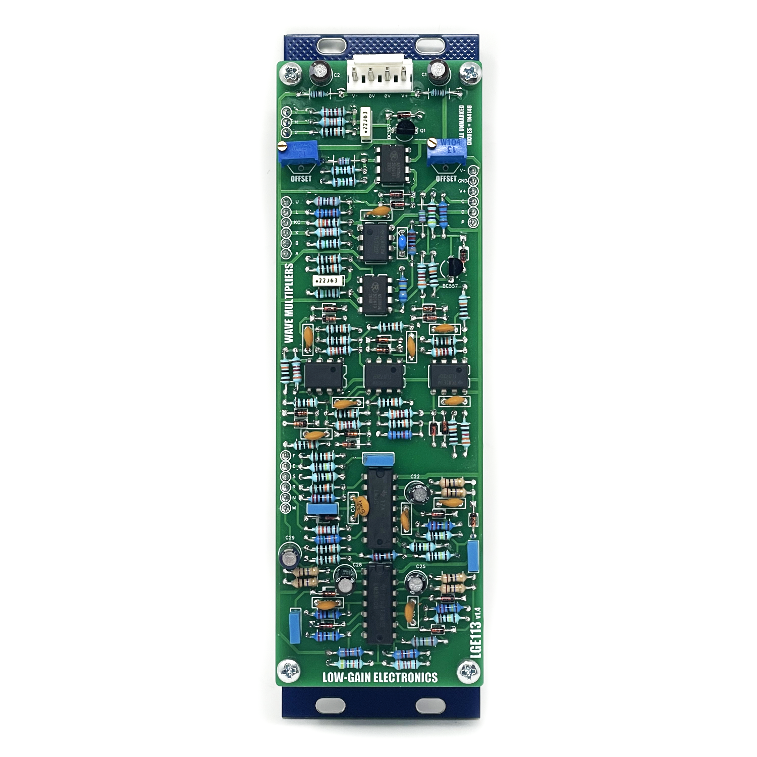
LGE113 Main Board Bill of Materials
LGE113 Main Board Schematic
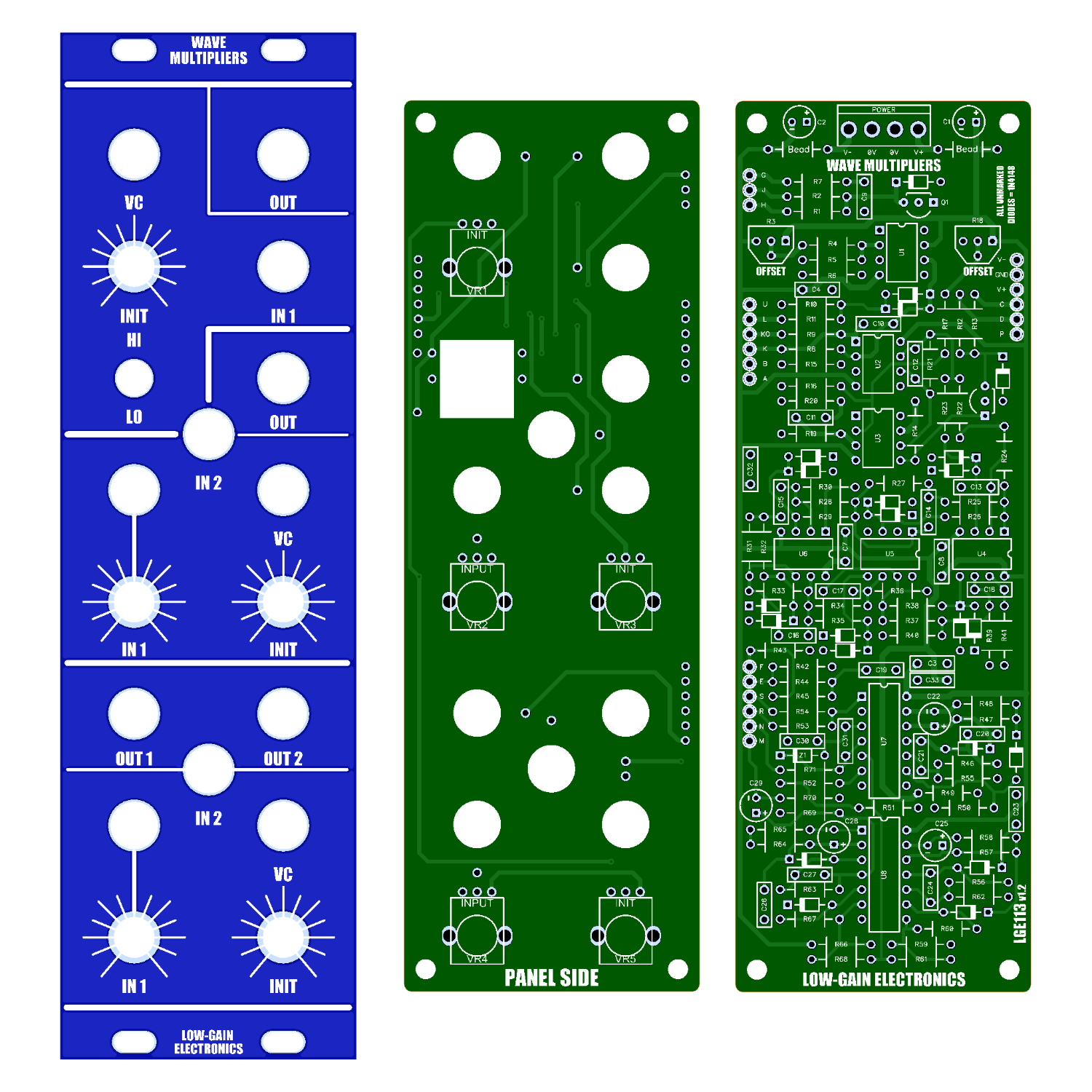
LGE113 Main Board Designator Layout (There is an error on LGE113 v1.2 pcb’s: The 3 Pin header w/ J, H and G are wired incorrectly between LGE113 and LGE113C. They will need to be connect with wires instead of male and female headers. v1.4 is ok w/o any modifications)
LGE113C I/O Board Bill of Materials
LGE113C I/O Board Schematic (Wiring Diagram)
LGE113C I/O Board Designator Layout
Mechanical Parts BOM generally required for building Low-Gain Electronics Modules
building note: Be sure PCB is clean when you finish assembling. I recommend cleaning with 99% Isopropyl alcohol. Sometimes flux can build up and cause unwanted noise/crackling.

Correct HI / LO switch wiring
Calibration Procedure:
Top Section Trim - Insert 1kHz audio signal into the VC input, monitor output via Oscilloscope or just listen to the output. Adjust R3 Trimmer (right side of pcb) for minimal CV bleed at output
Middle Section Trim - Insert 1kHz audio signal into the VC input, monitor output via Oscilloscope or just listen to the output. Adjust R18 Trimmer (left side of pcb) for minimal CV bleed at output
Details:
PCB Size: 6” x 2”
Current Draw: TBD