
 Image 1 of 4
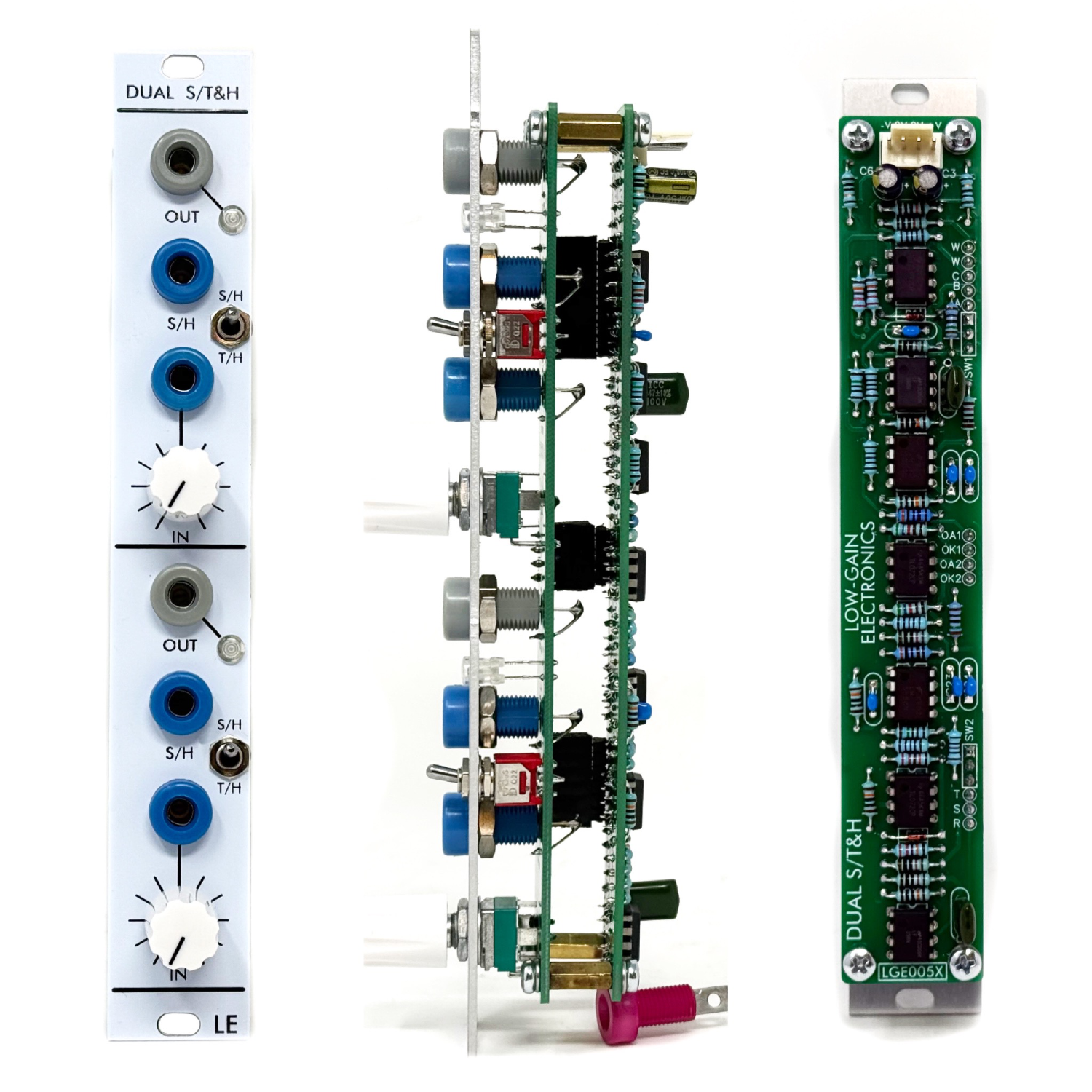 Image 2 of 4
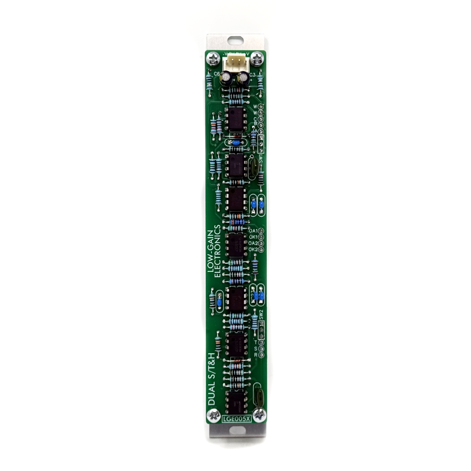 Image 3 of 4
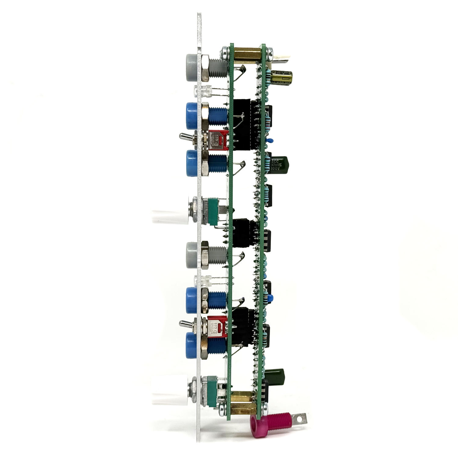 Image 4 of 4
Dual Sample / Track & Hold
Overview
The Dual Sample / Track & Hold module provides two independent voltage sampling circuits for control-voltage and audio applications. Each channel can operate as either a Sample & Hold or Track & Hold, allowing precise voltage capture, stepped modulation, rhythmic gating, and audio-rate processing.
Both channels operate independently and may be used simultaneously or in combination.
Panel Controls & Connections
Each channel includes the following controls and jacks:
IN: Signal input. Accepts both control voltages and audio signals.
OUT: Sampled or tracked output voltage. The output is buffered and may drive multiple destinations.
S/H INPUT: Control input used to trigger sampling or define tracking behavior, depending on the selected mode.
Mode Switch (S/H – T/H): Selects between Sample & Hold and Track & Hold operation for the channel.
Operation
Sample & Hold Mode
When the mode switch is set to S/H, the module samples the input voltage whenever the S/H Input goes high. The sampled voltage is held at the output until the next sampling event.
Typical uses include:
Stepped random voltages
Clocked modulation
Pitch sampling
Voltage capture on demand
Track & Hold Mode
When Track & Hold is selected, the output voltage follows the input as long as the input remains above approximately 1.3 V.
If the input drops below this threshold, the output enters hold and retains the previously tracked voltage.
The S/H Input may be left unpatched in Track mode, or used creatively to influence tracking behavior depending on the applied signal.
This mode is useful for:
Threshold-based voltage capture
Rhythmic modulation using envelopes or LFOs
Dynamic gating effects
Audio-Rate Operation
The module supports audio-rate signals and fast control sources. When driven at high frequencies, the Sample / Track & Hold circuits can produce stepped audio effects, sample-rate reduction, and other lo-fi textures.
Patching an audio signal into IN and driving the S/H Input with an oscillator or pulse source will produce quantized or “bit-crushed” audio outputs.
Patch Examples
Stepped Random CV
Patch a noise or random voltage source into IN and a clock or pulse generator into S/H Input. Use OUT to drive oscillators, filters, or VCAs.
Rhythmic Voltage Capture
Patch an envelope or LFO into IN and set the mode to TRACK. The output will follow the signal until it falls below the internal threshold, creating gated or rhythmic modulation.
Audio Sampling
Patch an audio source into IN and drive the S/H Input at audio rate to generate stepped or degraded audio textures.
Notes
Inputs and outputs are DC-coupled.
Both channels may be used independently or patched together.
LGE005 DIY Build Documentation:
LGE005X Bill of Materials (Contains both Main & I/O Boards)
LGE005X PCB Layout w/ Designators
LGE005X Schematic
LGE005XC Wiring Diagram / Schematic
LGE005XC I/O Board Layout w/ Designators
LGE005X Panel Layout (Art)
Mechanical Parts BOM generally required for building Low-Gain Electronics Modules
Serge Modular Ecosystem Compatibility
Modern Serge-style 4U systems use two primary mounting standards: Loudest Warning–style and Random*Source–style.
Low-gain Electronics modules follow the Loudest Warning–style mounting format (unless stated otherwise) and are electrically
compatible with all Serge-style systems, though mounting (panels) and power adapters may be required for some installations.
Please contact us if you have further questions about this.