
 Image 1 of 3
 Image 2 of 3
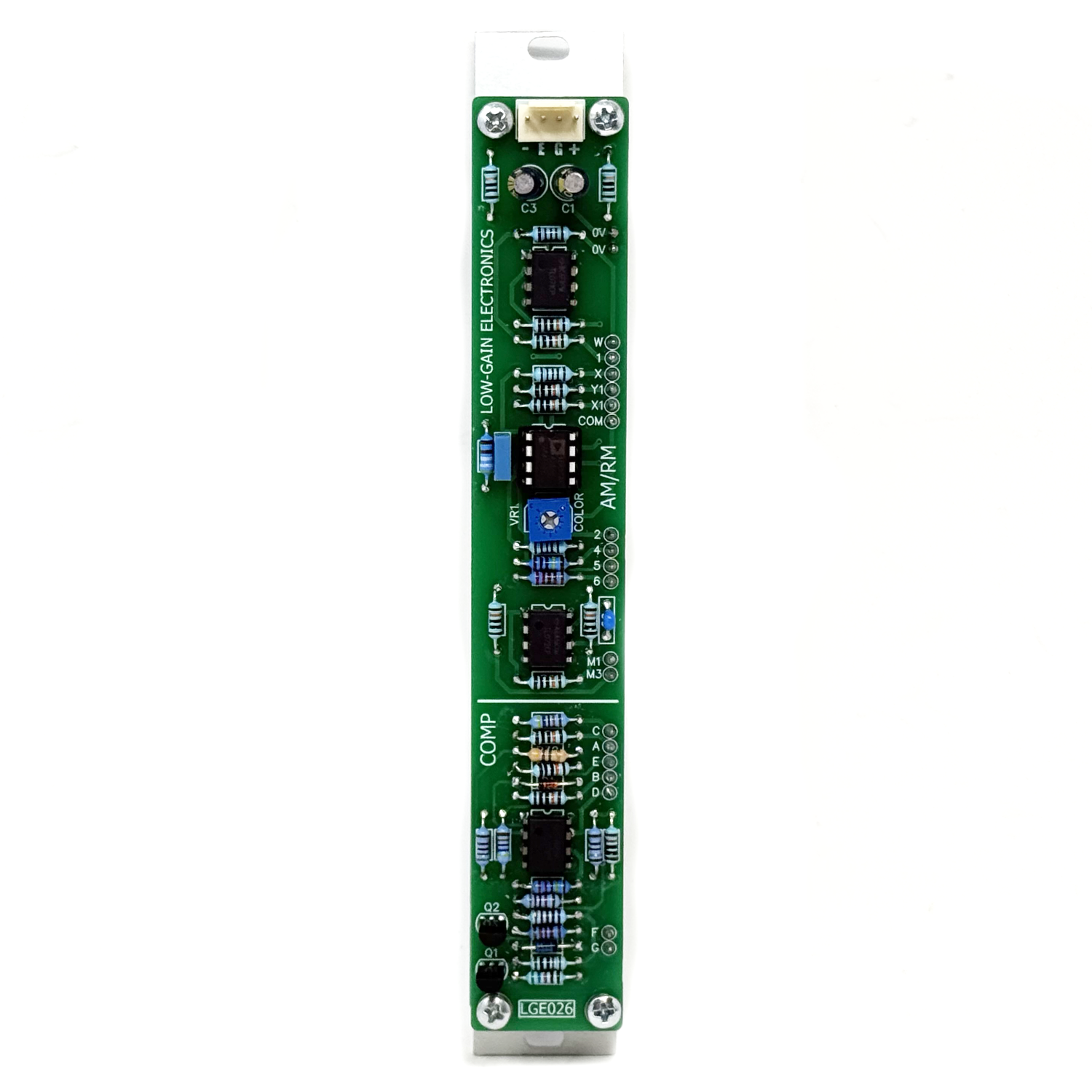 Image 3 of 3
LGE026 AM/RM + Comparator
Product Description
The Low-Gain Electronics LGE026 AM/RM + Comparator combines two versatile analog signal-processing functions in a compact 4U modular synthesizer module: an amplitude/ring modulator and a voltage comparator. The upper section features an AD633-based four-quadrant analog multiplier capable of amplitude modulation (AM) and balanced ring modulation (RM). Two incoming signals can be multiplied together to produce a wide range of effects, from conventional amplitude modulation and tremolo to complex harmonic and inharmonic sidebands, metallic textures, and bell-like tones.
In Ring Modulation mode, the circuit functions as a balanced modulator, multiplying the two incoming signals while ideally suppressing their original frequency components. In Amplitude Modulation mode, an additional signal component is introduced into the multiplier's output, with a dedicated CAR/MOD switch allowing either input to be selected for this purpose. The modulator input features a bipolar attenuverter, allowing the incoming signal to be continuously adjusted from inverted through zero to non-inverted. This provides control over modulation depth and polarity, expanding the range of available sounds and modulation behaviors. Beyond conventional audio processing, the DC-coupled four-quadrant multiplier can also be used for manipulating control voltages, making it useful for creating complex modulation relationships between oscillators, envelopes, LFOs, and other voltage sources.
The lower section features an independent voltage comparator with positive and negative inputs and an adjustable bipolar threshold. The comparator converts changing analog voltages into discrete logic states, making it useful for level detection, gate generation, pulse-width modulation, waveform conversion, and audio-rate logic processing.
Together, these two circuits offer a flexible combination of audio processing, voltage multiplication, and analog-to-logic conversion in a single module. Designed for 4U Serge-format modular synthesizer systems, the LGE026 is equally suited to traditional Serge patching techniques and experimental analog signal processing.
Circuit Description
AM/RM Section: The AM/RM section is built around an Analog Devices AD633 four-quadrant analog multiplier. The AD633 produces an output proportional to the product of two input signals, with an additional summing input that allows a selected signal to be introduced into the output. The multiplier operates according to the relationship: W = [(X1 − X2) × (Y1 − Y2)] / 10V + Z.
In Ring Modulation mode, the summing input (Z) is referenced to ground, allowing the circuit to function as a balanced modulator. The two incoming signals are multiplied together, producing sum and difference frequency components when audio-rate signals are applied. Ideally, the original carrier and modulator frequencies are suppressed, leaving only the multiplication products. The modulator input passes through a bipolar attenuverter before reaching the multiplier. This allows the modulation signal to be continuously varied from inverted through zero to non-inverted. At the center position, the modulation signal is minimized, ideally reducing the multiplication product to zero. Reversing the attenuverter's polarity reverses the polarity of the multiplication product, providing additional control over the resulting waveform.
In Amplitude Modulation mode, the AD633's summing input receives an additional signal derived from either the carrier or modulator input, selected by the CAR/MOD switch. This introduces a portion of the selected input alongside the multiplication products, producing a different modulation character.
The CAR/MOD selection is taken directly from the original input signals, before the MOD attenuverter. Consequently, selecting MOD in AM mode can allow some of the original modulator signal to remain at the output even when the attenuverter is centered at zero. The amount of signal introduced through the summing input is established by a resistor network with an adjustable COLOR trimmer. The multiplier output is then processed by a DC-coupled output amplifier, allowing the circuit to operate with both audio and control-voltage signals.
Although the inputs are identified as carrier and modulator, both are analog signal inputs and can be driven by audio-rate or low-frequency signals. Slowly changing control voltages can be multiplied together to produce more complex modulation signals, allowing one voltage to dynamically influence another.
Comparator Section
The comparator section uses TL072 operational amplifiers configured as a voltage-comparison circuit, with additional output circuitry providing a 0–5V logic signal. Separate positive (+) and negative (−) inputs allow incoming signals to be compared against one another, while the THRES control adjusts the circuit's operating threshold across a bipolar range extending toward the positive and negative supply rails. Increasing the voltage at the positive input favors the high output state, while increasing the voltage at the negative input favors the low output state. Both inputs can be used independently or simultaneously, allowing the comparator to respond to the relationship between two incoming voltages and the selected threshold.
When the effective switching threshold is crossed, the comparator changes output state, converting continuously varying analog voltages into discrete logic signals. Feedback provides controlled switching behavior near the threshold, while the output circuitry provides a positive-going 0–5V signal suitable for use as a gate or pulse. The comparator can process slowly changing control voltages as well as audio-frequency waveforms, making it useful for level detection, waveform conversion, pulse generation, and other voltage-dependent logic functions. When driven by an audio-frequency waveform, the comparator can also function as a waveform converter. Applying a sine, triangle, or sawtooth waveform produces a rectangular output, with the THRES control determining the switching point. Adjusting the threshold changes the resulting pulse width, allowing the comparator to operate as an audio-rate pulse generator or logic source.
Panel Functions
AM/RM Section
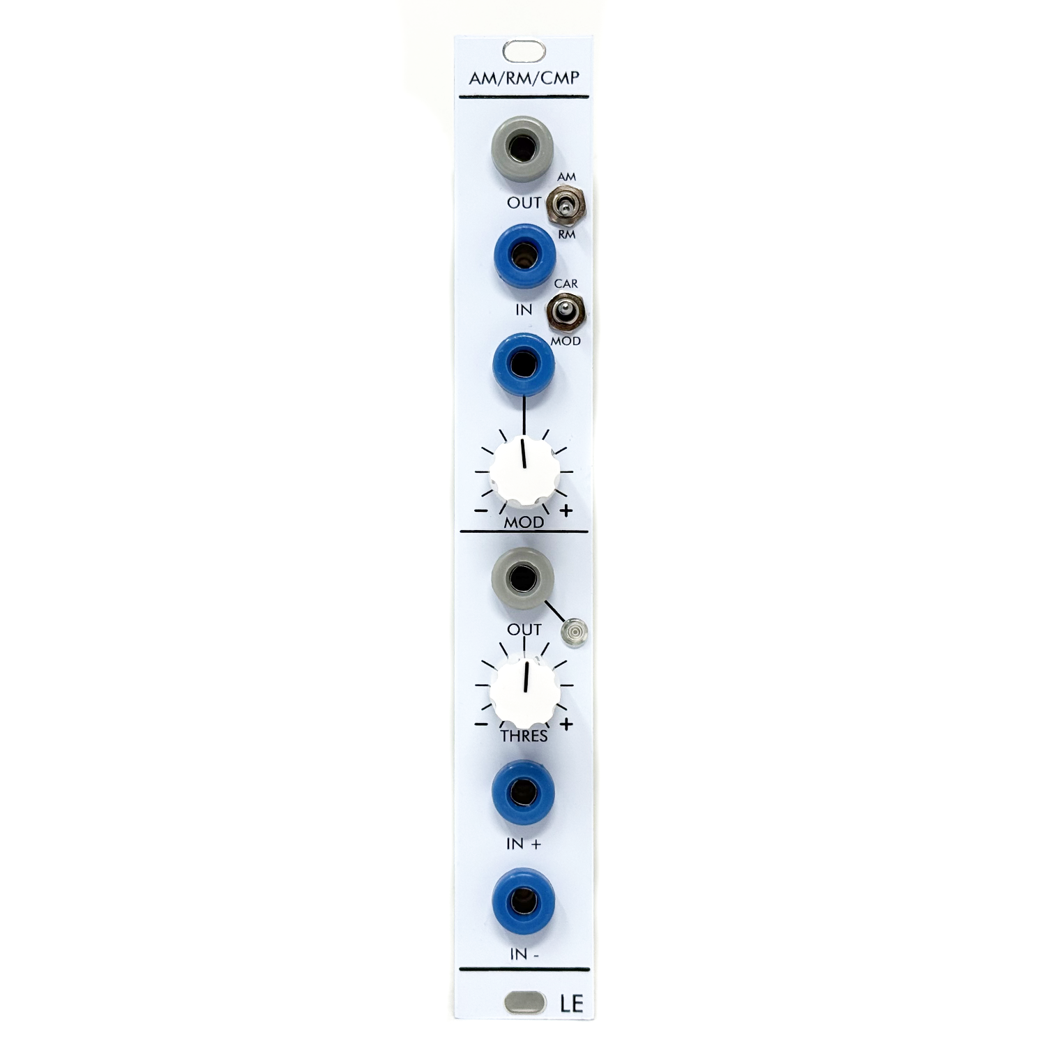
OUT (Output Jack): Output of the amplitude/ring modulation circuit. Provides the processed signal determined by the two inputs, MOD attenuverter setting, and selected operating mode.
AM/RM (Toggle Switch): Selects between Amplitude Modulation (AM) and Ring Modulation (RM). In AM mode, an additional signal component selected by the CAR/MOD switch is introduced into the multiplier's summing path. In RM mode, the additional summing path is grounded, allowing balanced multiplication of the two incoming signals.
IN (Carrier Input Jack): Carrier signal input. Accepts audio or control-voltage signals for the first multiplier input.
CAR/MOD (Toggle Switch): Selects which original input signal is introduced into the AD633's additional summing path when operating in AM mode. In the CAR position, a portion of the carrier signal is added to the multiplication product. In the MOD position, a portion of the original modulator input signal is added instead. The amount of the selected signal is determined by the internal COLOR adjustment.
Because the MOD selection is taken before the bipolar MOD attenuverter, some of the original modulator signal may remain present at the AM output even when the attenuverter is centered at zero. In RM mode, the additional summing path is grounded, so the CAR/MOD switch has no effect on the output.
MOD (Modulator Input Jack): Modulator signal input. Accepts audio or control-voltage signals for the second multiplier input.
MOD (Potentiometer): Bipolar attenuverter controlling the level and polarity of the incoming modulator signal. Fully counterclockwise provides maximum inverted modulation, the center position minimizes the modulation signal (ideally 0V), and fully clockwise provides maximum non-inverted modulation. This provides continuous control over modulation depth and polarity in both AM and RM modes.
Comparator Section
OUT (Output Jack): Comparator logic output. Produces a 0–5V signal depending on the relationship between the incoming voltages and the selected threshold. When driven by a changing waveform, the output can produce gates, pulses, or audio-rate rectangular waveforms.
LED Indicator: Displays the comparator output state, illuminating when the output is high.
THRES (Potentiometer): Adjusts the comparator's switching threshold across a bipolar voltage range extending toward the positive and negative supply rails. This allows the comparator to respond to different voltage levels at its positive and negative inputs. When processing audio-rate signals, adjusting THRES changes the switching point and can alter the pulse width of the resulting rectangular waveform.
IN + (Input Jack): Positive (non-inverting) comparator input. Increasing the voltage at this input favors the high output state. Useful for generating gates when a rising signal crosses the selected threshold.
IN − (Input Jack): Negative (inverting) comparator input. Increasing the voltage at this input favors the low output state. Useful for obtaining the opposite switching response from a rising signal.
Both comparator inputs may be used individually or simultaneously, allowing the circuit to respond to the relationship between two incoming voltages as well as the threshold setting.
Understanding AM and RM
Ring Modulation (RM): Ring modulation is a form of balanced modulation in which two incoming signals are multiplied together. When audio-rate signals are used, the output contains sum and difference frequency components, while the original input frequencies are ideally suppressed. This produces the characteristic metallic, bell-like, and often inharmonic sounds associated with ring modulation. Because the circuit uses a four-quadrant analog multiplier, it can process both positive and negative portions of the incoming signals.
Amplitude Modulation (AM): Amplitude modulation combines the multiplication products with an additional signal component. Unlike balanced ring modulation, the selected original signal remains present alongside the modulation products. The LGE026 allows either the carrier or modulator input to provide this additional component, expanding the available range of modulation effects. The MOD attenuverter provides continuous control over modulation depth and polarity, while the internal COLOR adjustment determines the amount of the additional signal introduced into the summing path.
Applications
Ring Modulation: Combine two audio signals to create sum and difference frequencies, metallic timbres, bell-like tones, and complex inharmonic textures.
Amplitude Modulation: Introduce carrier or modulator components for tremolo, animated textures, and variations on traditional amplitude modulation.
Audio-Rate Processing: Use oscillators, noise sources, and other audio signals to create complex modulation effects.
Control-Voltage Multiplication: Multiply slowly changing control voltages to create dynamically varying modulation signals.
Waveform Conversion: Use the comparator to convert triangles, sawtooths, sine waves, and other waveforms into rectangular or pulse signals.
Pulse-Width Modulation: Adjust the comparator threshold to change the duty cycle of a pulse waveform derived from a repeating input.
Level Detection: Generate a logic output when an incoming voltage crosses the selected threshold.
Gate and Rhythm Generation: Derive gates and rhythmic pulses from oscillators, envelopes, sequencers, and other control-voltage sources.
Analog Phase Detection: Multiply periodic signals and use external low-pass filtering to extract a voltage related to their phase difference.
Experimental Phase-Locked Loops: Use the AM/RM section as a phase detector in conjunction with an external loop filter and voltage-controlled oscillator.
Patching Ideas (subject to varification)
Classic Ring Modulation: Connect two oscillators to the carrier and modulator inputs. Select RM mode and adjust the MOD attenuverter to introduce the modulation signal. Experiment with different oscillator frequencies to create metallic tones, bell-like textures, and complex sidebands. Small changes in the relationship between oscillator frequencies can produce dramatic changes in the resulting timbre.
Amplitude Modulation and Tremolo: Connect an audio oscillator to the carrier input and a low-frequency oscillator to the modulator input. Select AM mode and use the CAR/MOD switch to explore different modulation characteristics. Adjust the MOD attenuverter to control the depth and polarity of the modulation.
Voltage Multiplication: Apply two slowly changing control voltages to the AM/RM inputs and select RM mode. The DC-coupled multiplier and output stage allow the output to follow the product of the two incoming voltages, within the circuit's operating range. For example, multiplying an LFO by an envelope can create a modulation signal whose amplitude changes over the duration of the envelope. The MOD attenuverter allows the multiplication to be adjusted from positive through zero to negative.
Audio-to-Pulse Conversion: Patch a triangle or sine-wave oscillator into the comparator's IN + input. Adjust THRES to change the switching point and produce rectangular waveforms with varying pulse widths. This technique can be used to derive pulse waveforms from oscillators that do not provide a dedicated pulse output.
Voltage-Controlled Gate Generation: Patch an envelope or slowly changing control voltage into the comparator. Adjust THRES to generate a gate whenever the incoming voltage crosses the selected threshold. This can be useful for triggering events at particular points during an envelope or modulation cycle.
Comparator-Driven Modulation: Patch the comparator output into the modulation input of another module, or back into the LGE026's modulation section. The comparator's 0–5V output can be used to switch or modulate the signal passing through the AM/RM section. Adjust the MOD attenuverter to control the amount and polarity of the resulting modulation. This arrangement is useful for rhythmic gating, audio-rate switching, and generating complex modulation patterns.
Analog Phase Detection: The LGE026's four-quadrant analog multiplier can be used as an analog phase detector when two periodic signals of the same frequency are applied to its inputs. Connect two sine-wave oscillators to the carrier and modulator inputs and select RM mode. Set the MOD attenuverter fully clockwise to pass the modulation signal without inversion. The multiplier produces a signal containing a component at twice the input frequency and a DC component related to the phase difference between the two signals. Pass the AM/RM output through an external low-pass filter to remove the higher-frequency component and extract a phase-dependent control voltage. For equal-frequency sine waves, the resulting average voltage follows a cosine relationship with their phase difference. The response is also influenced by the amplitudes of the incoming signals.
Comparator-Assisted Phase Detection: The comparator can be combined with the AM/RM section to create an alternative phase detector using sine and rectangular waveforms. Connect a sine-wave oscillator to the AM/RM carrier input. Connect a second oscillator to the comparator's IN + input, then patch the comparator output into the AM/RM modulator input. Select RM mode and adjust the MOD attenuverter to control the multiplication. Use the comparator's THRES control to establish the switching point of the second oscillator's waveform. The comparator converts the incoming waveform into a 0–5V rectangular signal, which is multiplied with the carrier signal by the AD633. Pass the resulting AM/RM output through an external low-pass filter to obtain a voltage related to the phase difference between the two oscillators. The comparator's unipolar output produces a different multiplication response from a bipolar square wave, allowing additional experimentation with phase-dependent signals.
Phase-Locked Loop Experiments: The LGE026 can serve as the phase-detection element in an experimental analog phase-locked loop. Apply a reference oscillator to one AM/RM input and the output of a voltage-controlled oscillator to the other. Select RM mode and route the AM/RM output through an external low-pass loop filter. Connect the filtered voltage to an appropriate frequency-control input on the voltage-controlled oscillator. As the phase relationship changes, the multiplier produces a corresponding change in the filtered control voltage. With suitable loop-filter characteristics, oscillator response, and feedback polarity, this voltage can be used to bring the oscillator into synchronization with the reference. The MOD attenuverter can be used to adjust the polarity and strength of the phase-detection signal. This application requires an external loop filter and a suitable voltage-controlled oscillator. The LGE026 functions as the phase detector rather than a complete phase-locked loop, and the multiplier does not provide independent frequency-error detection.
DIY Building Notes:
The LGE026 is designed for operation in ±12V modular synthesizer systems and uses an Analog Devices AD633 four-quadrant analog multiplier for amplitude and ring modulation, along with TL072 operational amplifiers for the modulation attenuverter and comparator circuitry. The AM/RM circuit is designed around typical Serge modular signal levels, with a bipolar MOD attenuverter that allows the incoming modulation signal to be adjusted from inverted through zero to non-inverted.
COLOR Adjustment: The AM/RM circuit includes an internal COLOR adjustment that controls the amount of the selected carrier or modulator signal introduced into the AD633's summing input when operating in AM mode. The standard configuration uses a 1M resistor at R31, providing a relatively subtle adjustment range. Builders wishing to experiment with a wider range of COLOR adjustment can substitute lower resistance values to increase attenuation and change the balance between the original signal and the multiplication products. Values such as 470k, 220k, or 100k may be explored depending on personal preference. These are optional modifications rather than required changes, and builders are encouraged to experiment to find the response that best suits their needs. The COLOR adjustment affects the additional signal introduced in AM mode and does not change the multiplier's fundamental operation in RM mode.
MOD Attenuverter: The MOD potentiometer operates as a bipolar attenuverter rather than a conventional attenuator. Its center position minimizes the modulation signal, while rotation in either direction increases the signal level with positive or inverted polarity. A small amount of signal feedthrough near the center position may occur due to normal component tolerances.
Comparator Operation: The comparator section uses TL072 operational amplifiers with adjustable bipolar threshold control and separate positive and negative signal inputs. Its output circuitry provides a 0–5V logic signal suitable for gate, pulse, and audio-rate switching applications. Builders can experiment with different input waveforms and threshold settings to explore the comparator's response and its use as an audio-rate logic processor.
General Building Considerations: The LGE026 uses banana jack connections and is intended for integration into compatible 4U modular synthesizer systems operating from ±12V DC power supplies. As with any DIY electronic project, component orientation, power connections, and solder joints should be checked carefully before applying power.
LGE026 AM/RM + Comparator DIY Information: (Coming soon)
LGE026 Bill of Materials (Contains both Main & I/O Boards)
LGE026 Main Board PCB w/ Designators
LGE026 Main Board Schematic
LGE026C I/O Board Schematic / Wiring Diagram
LGE026C I/O Board PCB w/ Designators
LGE026 Printable Panel Art
Mechanical Parts BOM generally required for building Low-Gain Electronics Modules
** 4U Modular is a term used for the format most commonly known as “Serge Format” or “Loudest Warning Format”. Out of respect for the ever growing format, 4U Modular is the easiest way to refer to it. More Specifically it refers to the panel height and mounting hole style. 4U Modular will patch up just fine with other 4U "Serge" formats such as "Random Source", but it will not mount in RS boats or Buchla Boats (or power off Buchla power for that matter). An info page about this will be added to the website soon to make this a lot more easy to understand.
Details:
PCB Size: 6” x 1”
Current Draw: TBD