
 Image 1 of 3
 Image 2 of 3
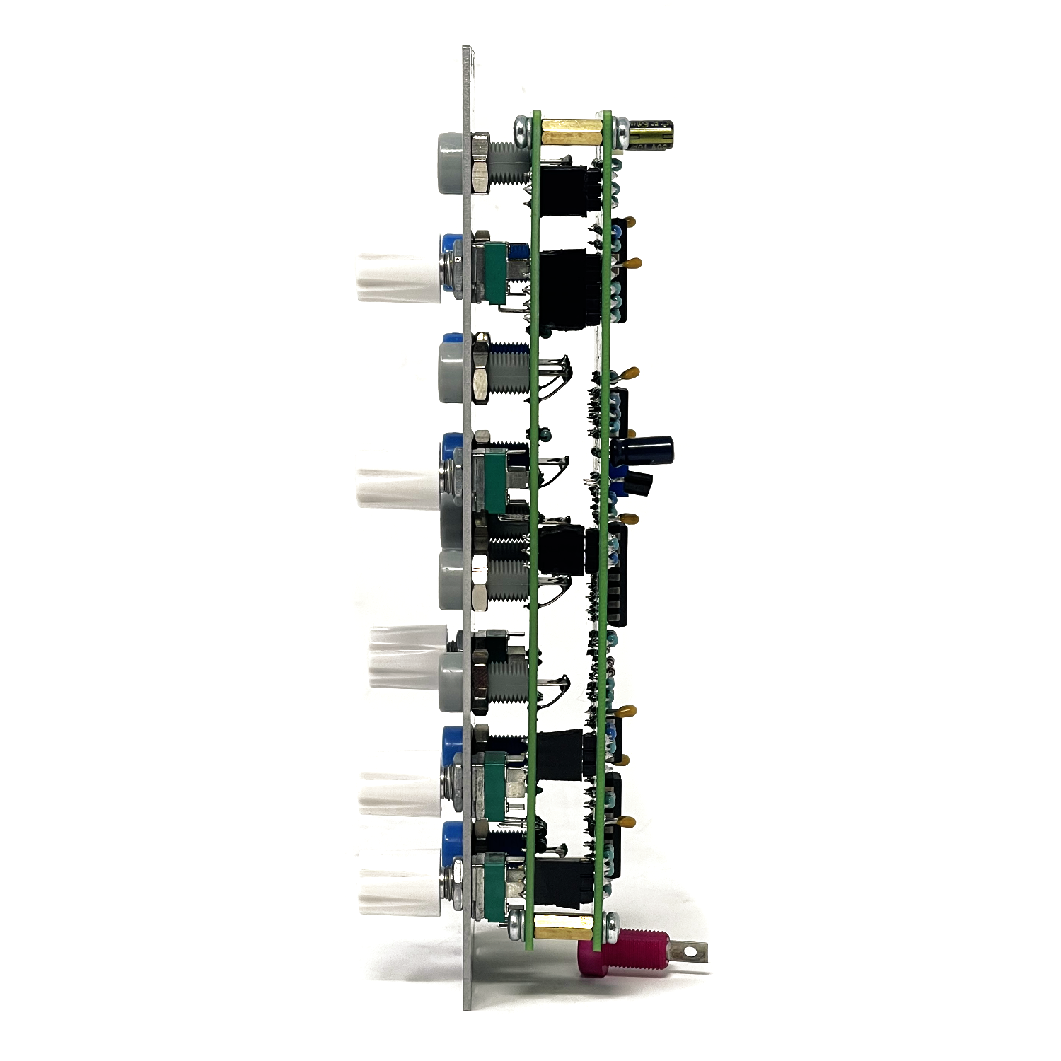 Image 3 of 3
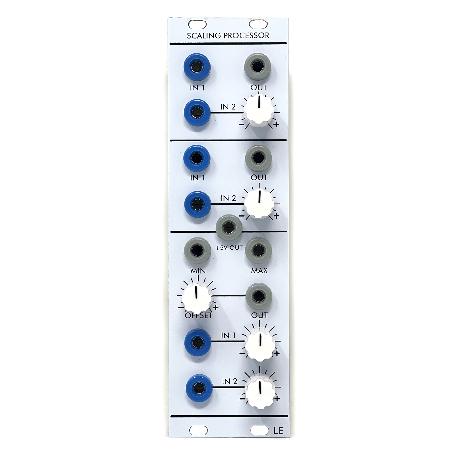
Scaling Processor is a compact, three-section voltage and audio utility inspired by the classic STS Scaling Processor found on the original CV Processor M-Class panel. Designed in the Serge tradition, this module focuses on clarity, flexibility, and hands-on control, making it an indispensable tool for shaping control voltages, audio signals, and modulation relationships in any 4U system.
The module provides three independent two-channel processing sections, each optimized for fast patching and intuitive signal conditioning. From simple attenuation and mixing to voltage range limiting and peak/trough extraction, Scaling Processors excels as a behind-the-scenes workhorse that quickly becomes central to complex patches.
A built-in stable+5V reference output is included for offsets, biasing, and quick utility duties anywhere in your system.
Key Features
Three independent processing sections
DC-coupled throughout (suitable for CV and audio)
Bipolar attenuation on all controlled inputs
Dedicated +5V reference output
Serge-compatible 4U format and signal levels
Section Overview
Top Processor
One bipolar attenuated input
One non-attenuated input
Single summed output
Ideal for quick scaling and mixing where one signal needs precise level control while another passes at unity gain.
Middle Processor
One bipolar attenuated input
One non-attenuated input
Single summed output
Functionally identical to the top processor, allowing parallel or cascaded processing for more complex voltage shaping.
Bottom Processor
Two bipolar attenuated inputs
Dedicated ±5V offset control
MIN output (lowest voltage of the two inputs)
MAX output (highest voltage of the two inputs)
SUM output (standard mixed output)
This section operates similarly to a classic Peak & Trough processor, enabling dynamic voltage comparison, range limiting, and logic-like CV behavior while still offering traditional mixing.
+5V Output
A precision +5V reference source is provided for:
Adding fixed offsets
Biasing CV paths
Creating manual modulation sources
Feeding processors that expect a known reference voltage
This voltage is internally stable and designed to be safely used throughout a Serge-style system. LOW-LGE030C-SCH
User Manual
Signal Compatibility
Accepts audio and control voltages
Designed for Serge-level signals
Fully DC-coupled signal path
Attenuation Controls
All attenuated inputs are bipolar, allowing:
Positive scaling
Negative inversion
Complete signal nulling
Center position corresponds to zero gain.
Offset Control (Bottom Processor)
The OFFSET knob introduces a variable DC voltage (±5V range) into the bottom processor’s signal path. This is especially useful for:
Shifting LFOs into unipolar ranges
Biasing random voltages
Creating windowed modulation effects when combined with MIN/MAX outputs
MIN / MAX Outputs
MIN outputs the lowest instantaneous voltage of the two inputs
MAX outputs the highest instantaneous voltage of the two inputs
Common uses include:
CV range limiting
Envelope following and comparison
Creating stepped or conditional modulation paths
Generative and logic-style patches without digital logic
Patch Examples
Classic Scaling
Patch an LFO into an attenuated input
Use the output to precisely control modulation depth
Offset Random Voltages
Patch a random source into the bottom processor
Use OFFSET to shift the voltage range
Extract MIN or MAX for constrained randomness
CV Logic / Windowing
Patch two envelopes into the bottom processor
Use MAX to select the dominant contour
Use MIN for inverse or subtractive motion
Audio Mixing
Mix two oscillators or waveforms
Apply bipolar attenuation for phase inversion and blending
Design Notes
Scaling Processor follows the philosophy of the original Serge and STS utilities: simple building blocks that reveal deeper functionality through patching. Rather than prescribing behavior, the module encourages experimentation, making it equally valuable for beginners and experienced patchers.
Internally, the design adheres to proven Serge-style topologies and precision reference handling as shown in the module schematics, ensuring stable operation and predictable results in performance and studio environments.
LGE030 Scaling Processor DIY Build Documenation:
LGE030 Bill of Materials (Contains both Main & I/O Boards)
LGE030 PCB Layout w/ Designators
LGE030 Main Board Schematic
LGE030C I/O Board Layout w/ Designators
LGE030C I/O Board Schematic (Wiring Diagram)
LGE030 Panel Layout (Art)
Mechanical Parts BOM generally required for building Low-Gain Electronics Modules
Calibration: Monitor Minimum Processor output with volt meter. Adjust Offset Trimmer so that it reads as close to 0V as possible.
Serge Modular Ecosystem Compatibility
Modern Serge-style 4U systems use two primary mounting standards: Loudest Warning–style and Random*Source–style.
Low-gain Electronics modules follow the Loudest Warning–style mounting format (unless stated otherwise) and are electrically
compatible with all Serge-style systems, though mounting (panels) and power adapters may be required for some installations.
Please contact us if you have further questions about this.