
 Image 1 of 5
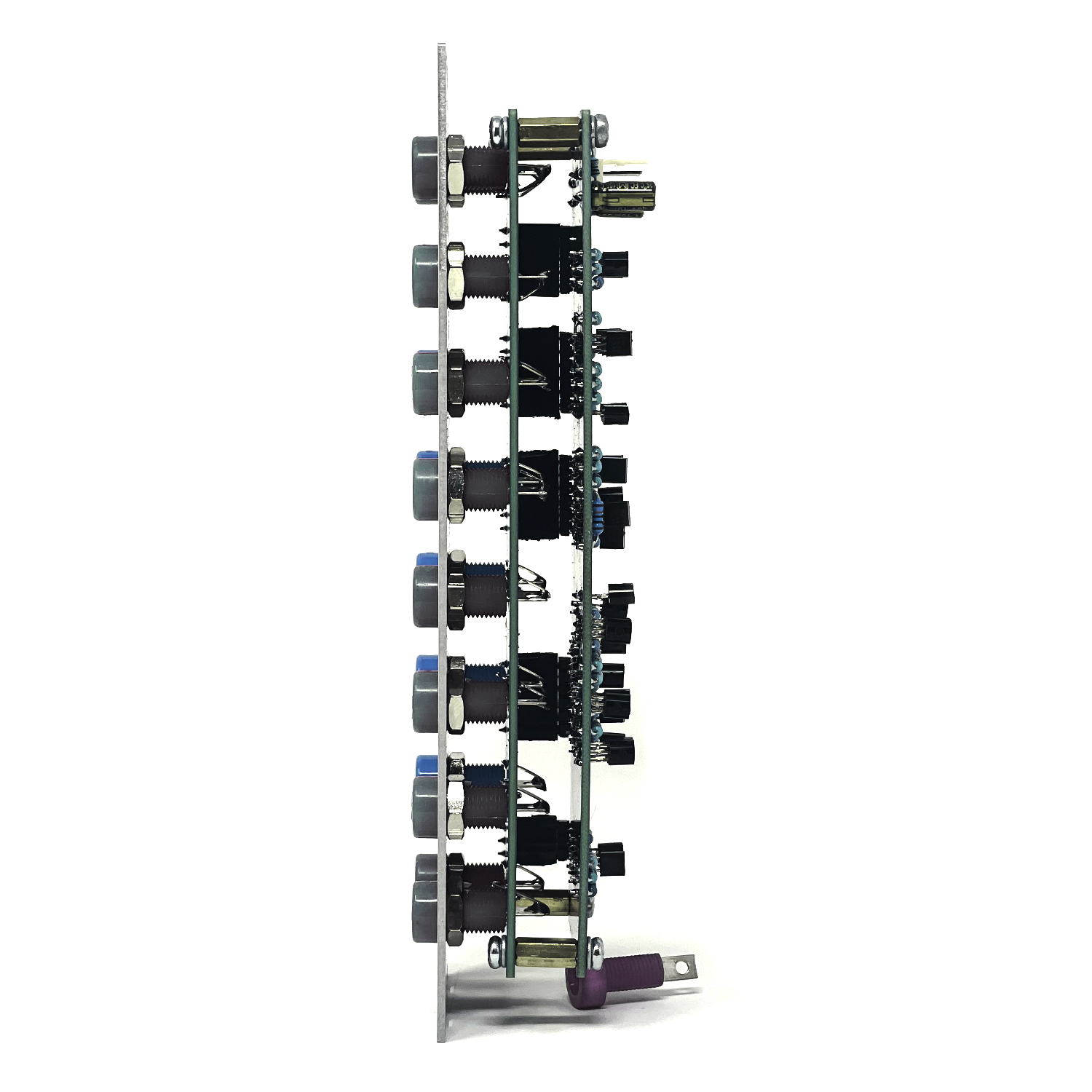 Image 2 of 5
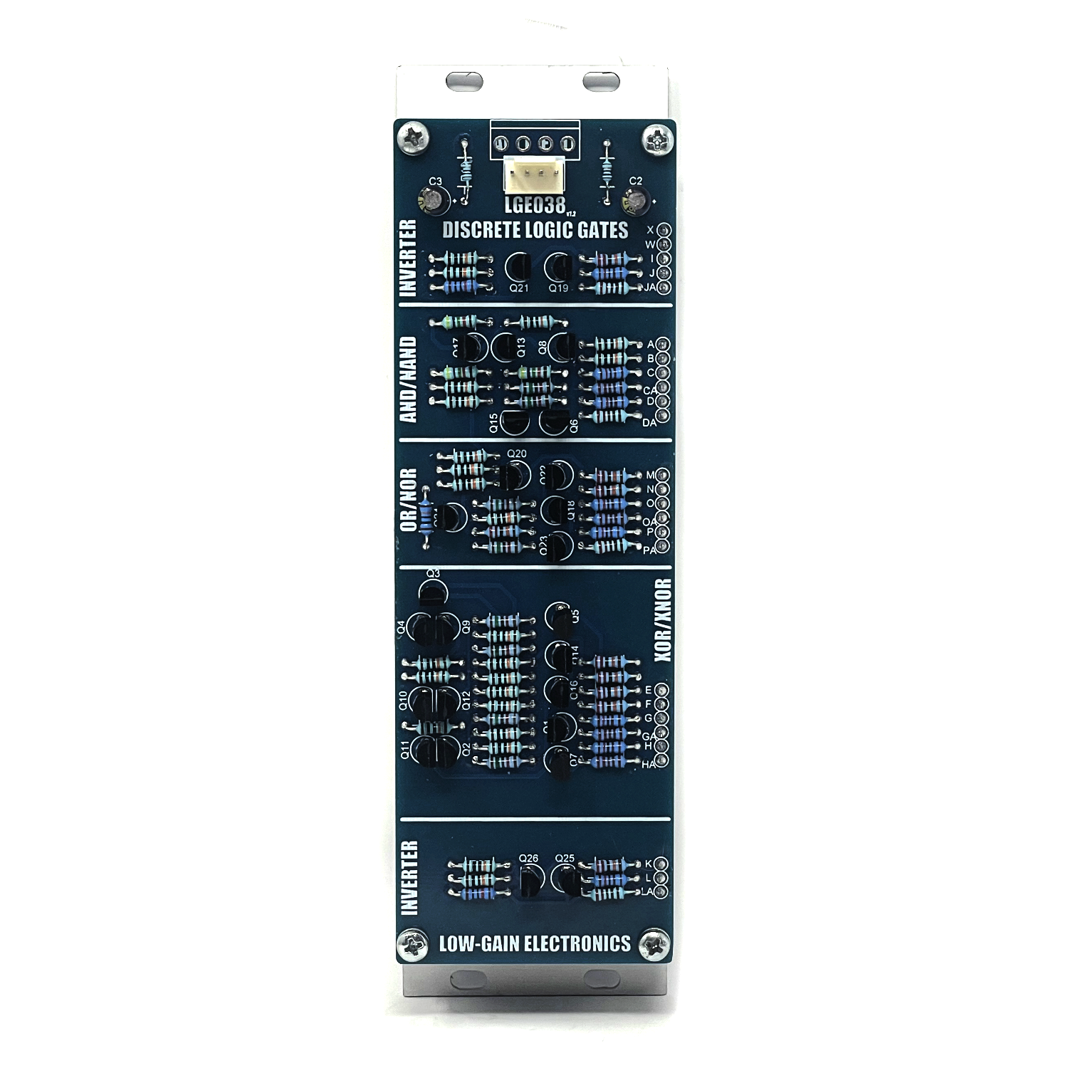 Image 3 of 5
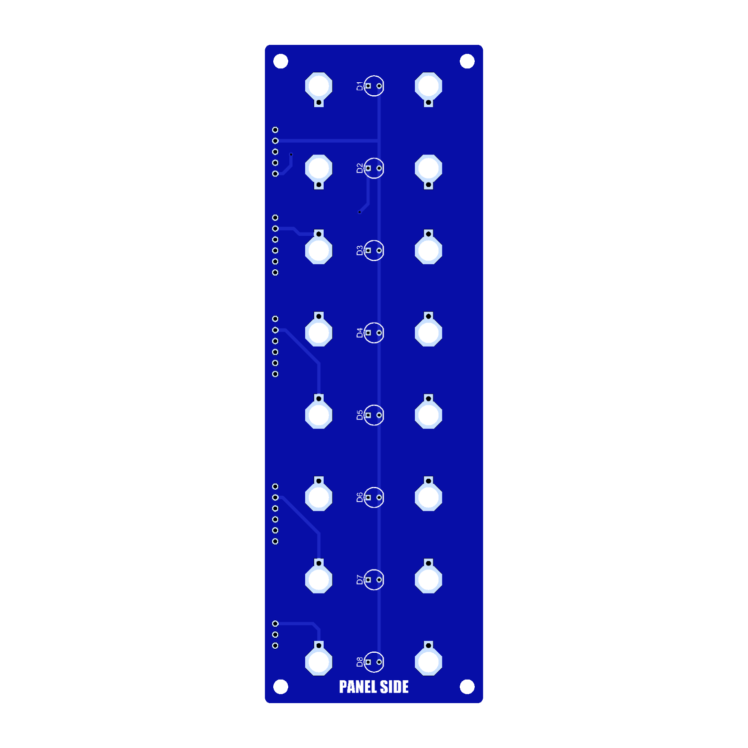 Image 4 of 5
 Image 5 of 5
Discrete Logic – Analog Logic Gate Processor for Modular Synthesis
The Discrete Logic module is a versatile toolkit of six essential logic gates and two inverters, built entirely from discrete transistors. Free from integrated circuits, this all-analog module offers ultra-fast signal processing with a character all its own—ideal for audio and CV manipulation in a Eurorack system.
Module Layout
Top & Bottom Sections – Logic Inverters (NOT gates):
These sections flip incoming gate or pulse signals—turning high into low and vice versa. Excellent for generating inverse clocks, off-beat rhythms, or logic-controlled signal cancellation.
Logic Gates & Truth Tables
AND Gate
Outputs high (1) only when both inputs are high.
| Input A | Input B | Output |
|---------|---------|--------|
| 0 | 0 | 0 |
| 0 | 1 | 0 |
| 1 | 0 | 0 |
| 1 | 1 | 1 |
Use Case: Combine two clocks or gates—great for conditional sequencing, or layering rhythms that only fire when multiple sources are active.
NAND Gate
The inverse of AND: outputs low only when both inputs are high.
| Input A | Input B | Output |
|---------|---------|--------|
| 0 | 0 | 1 |
| 0 | 1 | 1 |
| 1 | 0 | 1 |
| 1 | 1 | 0 |
Use Case: Introduce “always-on unless...” behavior to a patch, or create bursts of rhythm when conditions are not met.
OR Gate
Outputs high when either input is high.
| Input A | Input B | Output |
|---------|---------|--------|
| 0 | 0 | 0 |
| 0 | 1 | 1 |
| 1 | 0 | 1 |
| 1 | 1 | 1 |
Use Case: Merge gate signals from different sources—useful for combining triggers from manual buttons, sequencers, or random gates.
NOR Gate
The inverse of OR: outputs high only when both inputs are low.
| Input A | Input B | Output |
|---------|---------|--------|
| 0 | 0 | 1 |
| 0 | 1 | 0 |
| 1 | 0 | 0 |
| 1 | 1 | 0 |
Use Case: Use NOR gates to add silence or create gating logic that responds only when no inputs are active.
XOR (Exclusive OR) Gate
Outputs high only when one input is high and the other is low.
| Input A | Input B | Output |
|---------|---------|--------|
| 0 | 0 | 0 |
| 0 | 1 | 1 |
| 1 | 0 | 1 |
| 1 | 1 | 0 |
Use Case: Useful for rhythm offsetting, CV modulation gating, or even audio-rate waveform mixing to create interesting textures.
XNOR Gate
The inverse of XOR: outputs high only when both inputs are the same.
| Input A | Input B | Output |
|---------|---------|--------|
| 0 | 0 | 1 |
| 0 | 1 | 0 |
| 1 | 0 | 0 |
| 1 | 1 | 1 |
Use Case: Sync gates and modulations; create triggers only when two sources are in agreement—great for phase alignment or logic-based CV filtering.
Visual Feedback & Creative Potential
Each output features a dedicated status LED to clearly indicate the logic state in real time—perfect for live patching and debugging complex setups.
Creative Applications:
Generative Rhythms: Patch in clocks, random gates, or sequencer outputs to create evolving and conditional patterns.
Signal Filtering & Cleanup: Use logic to clean up noisy or overlapping gates.
Audio Rate Mayhem: XOR and NAND gates can be used as wave-shaping tools when fed audio signals—explore raw, gritty sound design.
Modulation Routing: Control when and how modulation reaches a destination based on logic conditions.
Discrete Logic transforms simple gates into complex musical ideas. Whether you're building intricate generative systems or sculpting chaotic audio textures, this analog logic powerhouse opens new doors in your modular journey.
Benefits of Transistor-Based (Discrete) Logic Gates
1. Faster Analog Signal Response
Why it matters: Discrete transistor logic can switch faster with analog signals, especially with sharp rising and falling edges. This makes it better suited for processing high-speed pulses or audio-rate signals without the sluggish behavior that can occur in some CMOS chips.
2. Continuous Voltage Behavior (Not Just Binary)
Discrete transistor logic tends to respond more gradually or dynamically to input voltages, whereas CMOS logic has strict voltage thresholds.
Use case in modular: You can exploit non-binary signal behavior for wave shaping, modulation blending, or "gray area" logic, leading to more nuanced or unexpected results—great for experimental patches.
3. No Internal Clamping or Hysteresis
Many CMOS gates have built-in input protection, clamping diodes, or hysteresis to ensure digital cleanliness—but these features can interfere with analog behavior or cause "dead zones."
Discrete logic gives you unfiltered access to the circuit's behavior, enabling unique CV mangling and real-time control.
4. Saturation & Distortion Possibilities
Transistor logic can distort or saturate in ways that are sonically interesting, especially with audio-rate signals.
CMOS is clean and precise; discrete logic is raw and characterful—this can turn a logic module into a creative sound-shaping tool.
5. Voltage Flexibility
Discrete designs can be tailored to work across a wider or more unusual voltage range than standard 5V CMOS gates.
This is particularly useful in modular synths, where gate and CV voltages vary (e.g., 0–8V, ±5V, etc.).
Trade-offs vs. CMOS Logic Gates
| Feature | Discrete Transistor Logic | CMOS Logic Gates |
| Speed | Very fast, analog-capable | Fast, but mostly for digital signals |
| Power Consumption | Typically higher | Very low |
| Build Complexity | More components, larger circuit | Compact, all-in-one ICs |
| Behavior | Continuous, imperfect, expressive | Strict digital thresholds |
| Sonic Character | Gritty, raw, possibly nonlinear | Clean and controlled |
| Cost / Size | More expensive and larger | Small, cheap |
Why Choose Discrete Logic in Modular?
You’re not just using logic for utility—you’re using it as a creative instrument.
Discrete logic brings unpredictability, subtle control, and an organic feel that’s hard to replicate with CMOS.
Perfect for artists who want characterful gates, audio-rate logic interaction, or modulation with personality.
** 4U Modular is a term used for the format most commonly known as “Serge Format” or “Loudest Warning Format”. Out of respect for the ever growing format, 4U Modular is the easiest way to refer to it. More Specifically it refers to the panel height and mounting hole style. 4U Modular will patch up just fine with other 4U "Serge" formats such as "Random Source", but it will not mount in RS boats or Buchla Boats (or power off Buchla power for that matter). An info page about this will be added to the website soon to make this a lot more easy to understand.
LGE038 DIY Build Information: V1 pcb building… there is a board error where one leg of Q17 isn’t grounded and leaves AND output at a Logic HIGH.. To fix this, simply run a jumper or scratch the mask off the ground plane and connect Pin 1 to ground.
LGE038 Main Board Bill of Materials
LGE038 Main Board Schematic_V1.0
LGE038 Main Board V1.0 AND/NAND Output Modification
LGE038 Main Board Schematic V1.1 (Board not available yet, but shows the error on the V1.0 PCB)
LGE038 Main Board Designator Layout
LGE038C I/O Board Bill of Materials
LGE038C I/O Board Designator Layout
LGE038C Main Board Schematic / Wiring Diagram
Mechanical Parts BOM generally required for building Low-Gain Electronics Modules
Details:
PCB Size: 6” x 2”
Current Draw: TBD