
 Image 1 of 4
 Image 2 of 4
 Image 3 of 4
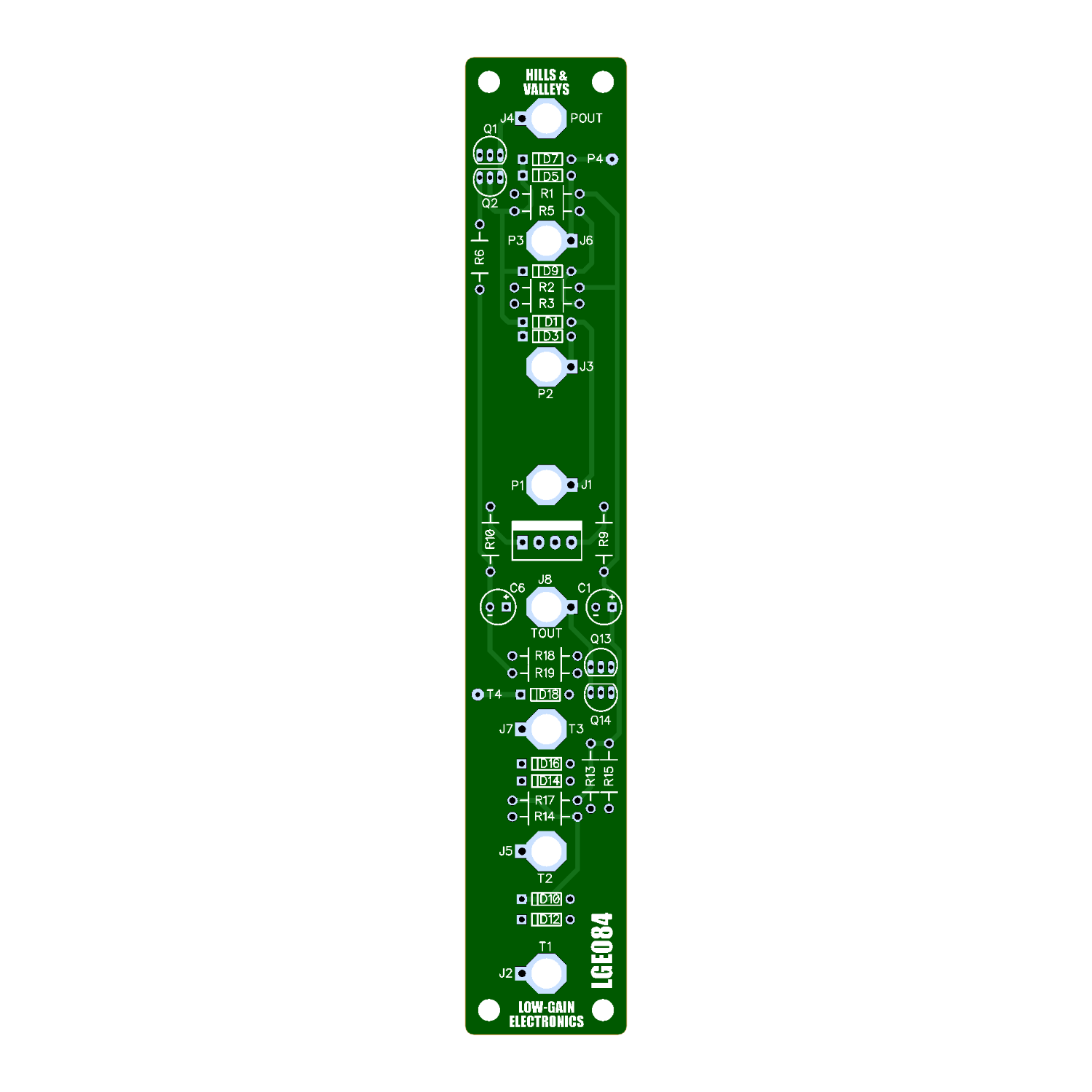 Image 4 of 4
The LGE084 Peak & Trough is a modern implementation of the classic Serge Peak & Trough circuit, originally developed in 1973. It provides two simple but powerful forms of analog voltage processing: Peak selects the highest instantaneous voltage present at its inputs, while Trough selects the lowest.
Unlike a conventional mixer, the inputs are not summed together. Instead, the output continuously follows whichever input is currently the highest or lowest voltage. This makes Peak & Trough useful for combining and reshaping control voltages, envelopes, LFOs, sequencer patterns, and other modulation sources.
With gate and pulse signals, the functions can also be used as a form of analog logic. Peak behaves similarly to an OR function, going high when one or more inputs are high, while Trough can provide AND-like behavior when the input signals share compatible voltage levels.
The LGE084 retains the simple discrete diode-and-transistor architecture of the original Serge design, updated for operation from standard ±12V 4U Modular power.
Circuit Description
The Peak and Trough sections use complementary diode-selection networks followed by discrete transistor stages.
The Peak circuit functions as an analog maximum selector. Its diode network allows the highest input voltage to take control of the common node, with the following transistor stage compensating for the diode voltage drop and buffering the resulting output.
The Trough circuit operates in the opposite direction. Its reversed diode network selects the lowest voltage present among its inputs, with its transistor stage providing corresponding diode-drop compensation and output buffering.
The LGE084 operates from ±12V supplies and uses a regulated +6V reference for internal biasing. Local power supply filtering and decoupling are also provided.
The circuit intentionally retains the straightforward analog architecture of the original Serge design rather than implementing a precision mathematical MAX/MIN processor.
V1: An error was found on the current pcb on the Hills/Valleys circuit. R5 connects to the nodes between pin 2 of Q2 and Ground. The Ground side of R5 should actually connect to V-. See Photo
V2: STILL ERRORS!? Just a simple Ground trace shorting the OR bus of the Hills (Peak) section of the pcb (top half of pcb). See edits below. Just have to cut a trace on the bottom SIDE of the pcb. See Photo
** 4U Modular is a term used for the format most commonly known as “Serge Format” or “Loudest Warning Format”. Out of respect for the ever growing format, 4U Modular is the easiest way to refer to it. More Specifically it refers to the panel height and mounting hole style. 4U Modular will patch up just fine with other 4U "Serge" formats such as "Random Source", but it will not mount in RS boats or Buchla Boats (or power off Buchla power for that matter). An info page about this will be added to the website soon to make this a lot more easy to understand.
LGE084 Peak & Trough (Hilles&Valleys) DIY Build Info:
LGE084 V1 Info
LGE084 Main Board Bill of Materials
LGE084 Main Board Schematic
LGE084 Main Board Designator Layout
LGE084 V2 Info
LGE084 V2 Error Fix (Rendered Fix)
LGE084 V2 Error Fix (Board Photo)
LGE084 V2 Main Board Designator Layout
LGE084 V2.1 Info
LGE084 V2.1 Main Board Bill of Materials
LGE084 V2.1 Main Board Schematic
LGE084 V2.1 Main Board Designator Layout
Mechanical Parts BOM generally required for building Low-Gain Electronics Modules
Details:
PCB Size: 6” x 1”
Current Draw: TBD