
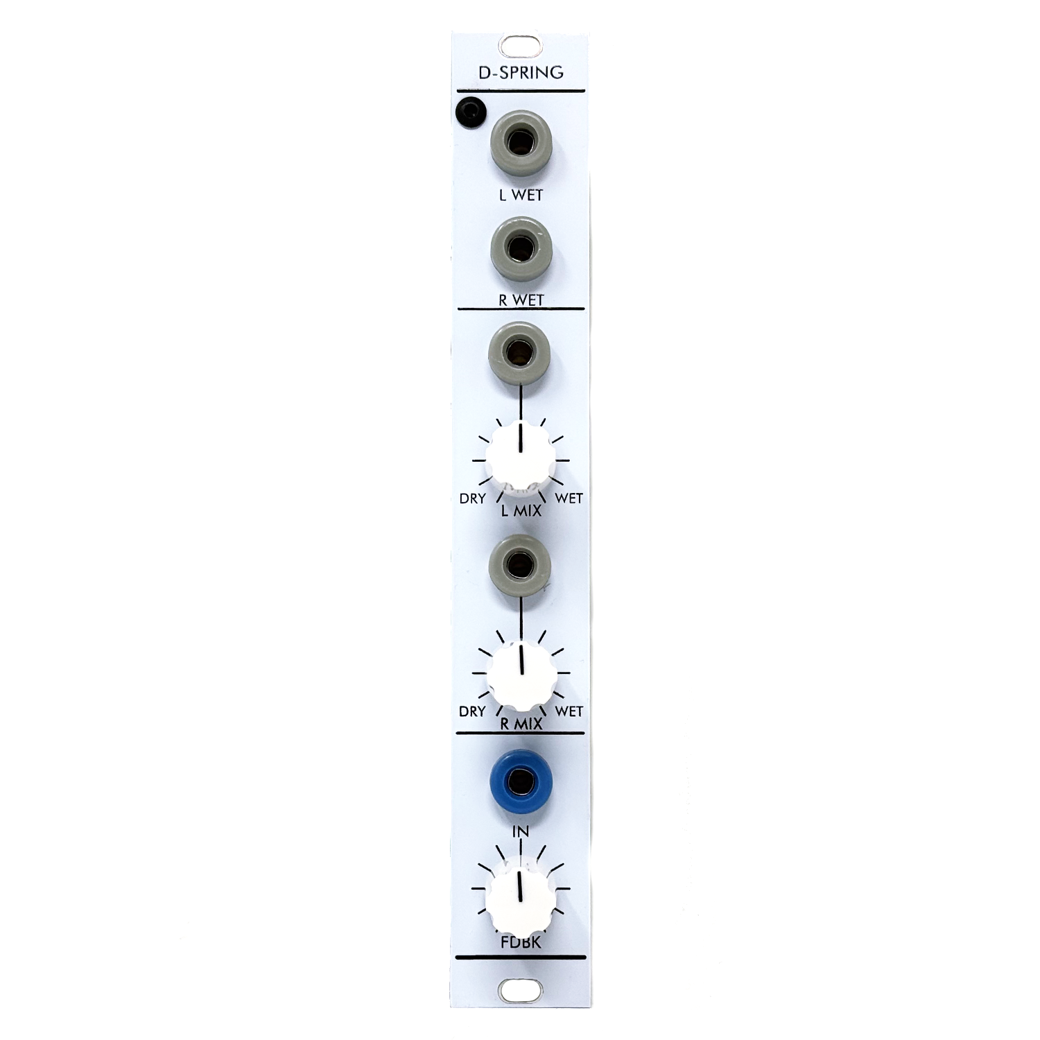
 Image 1 of 6
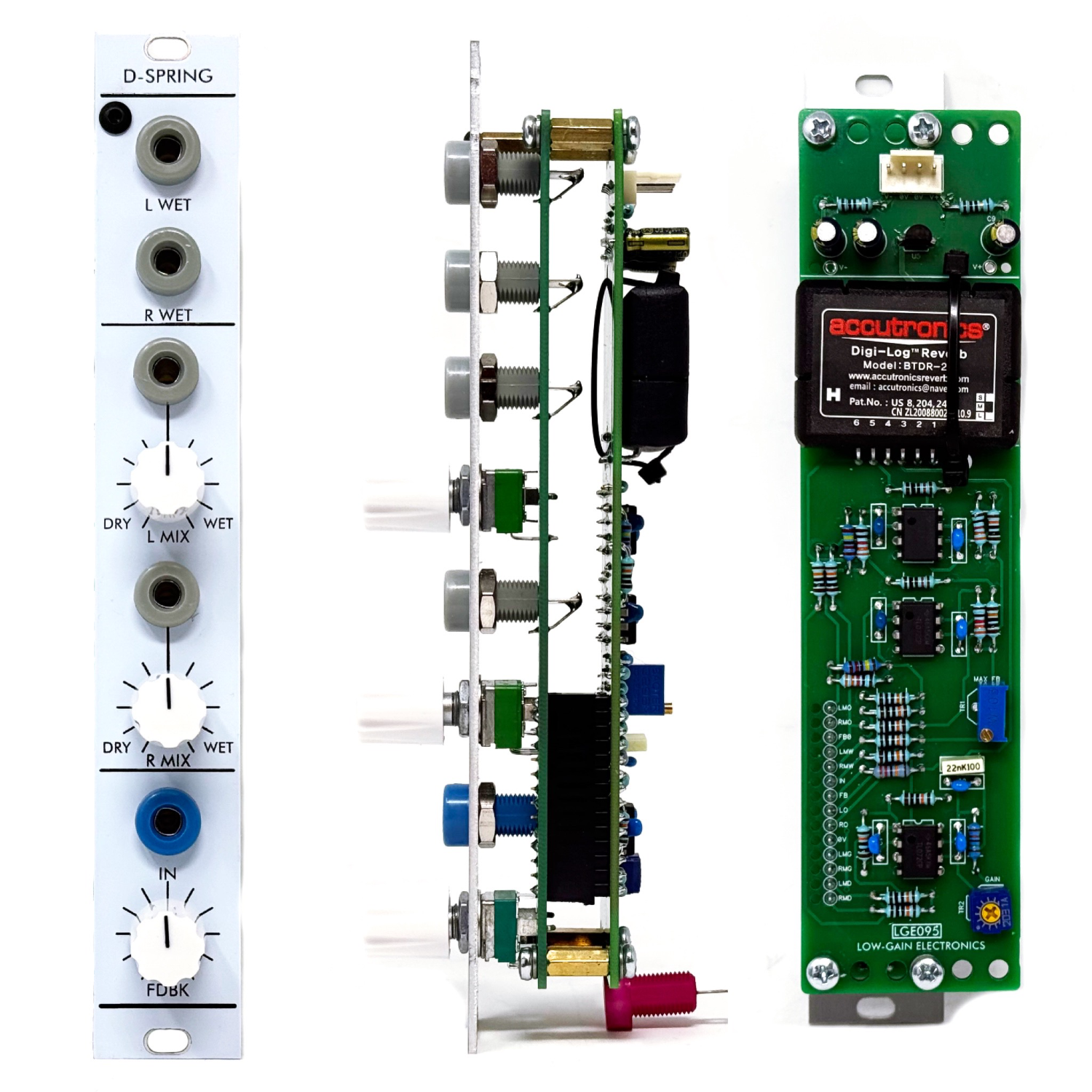 Image 2 of 6
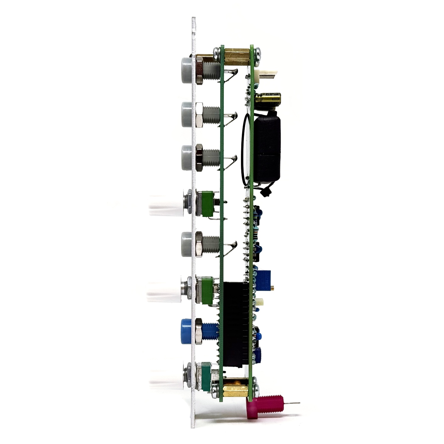 Image 3 of 6
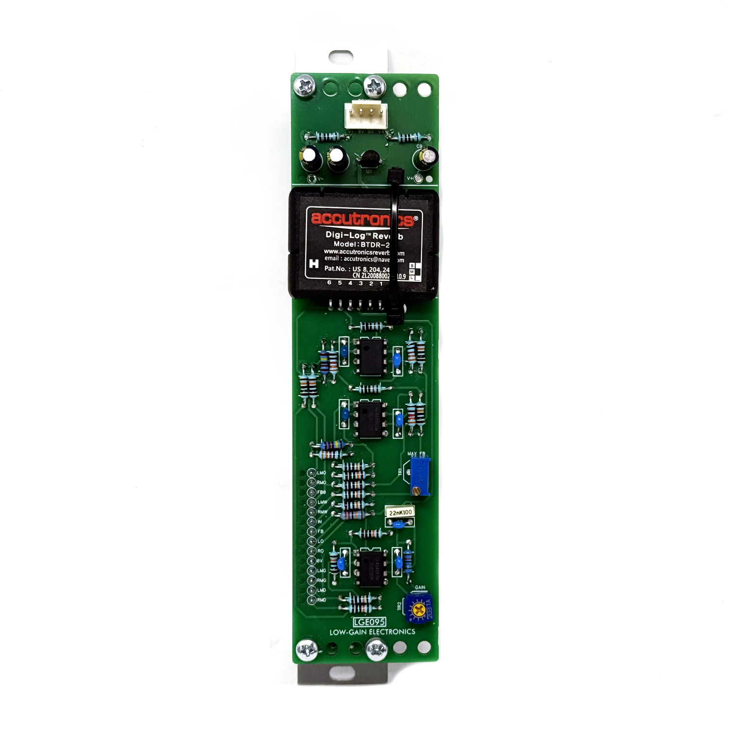 Image 4 of 6
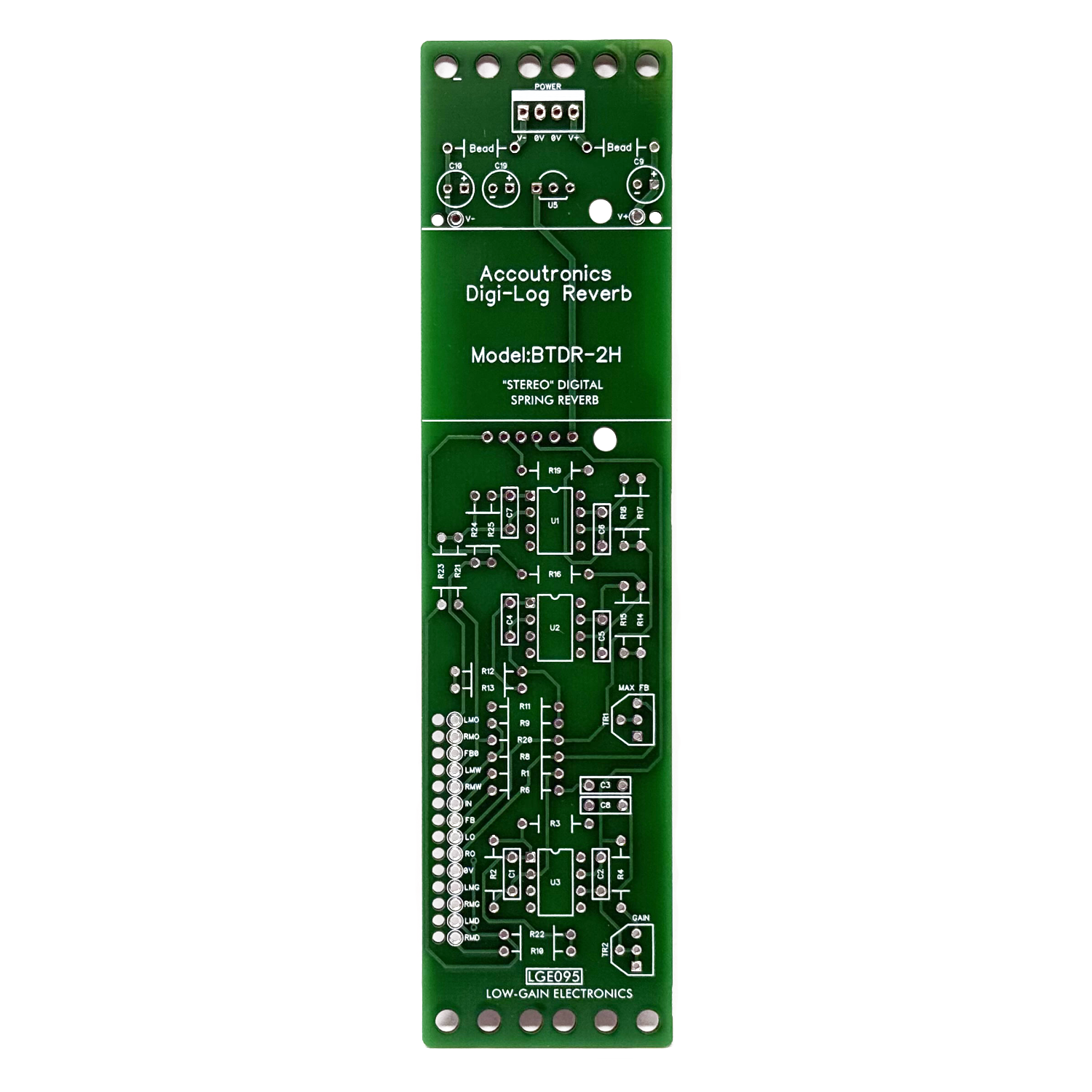 Image 5 of 6
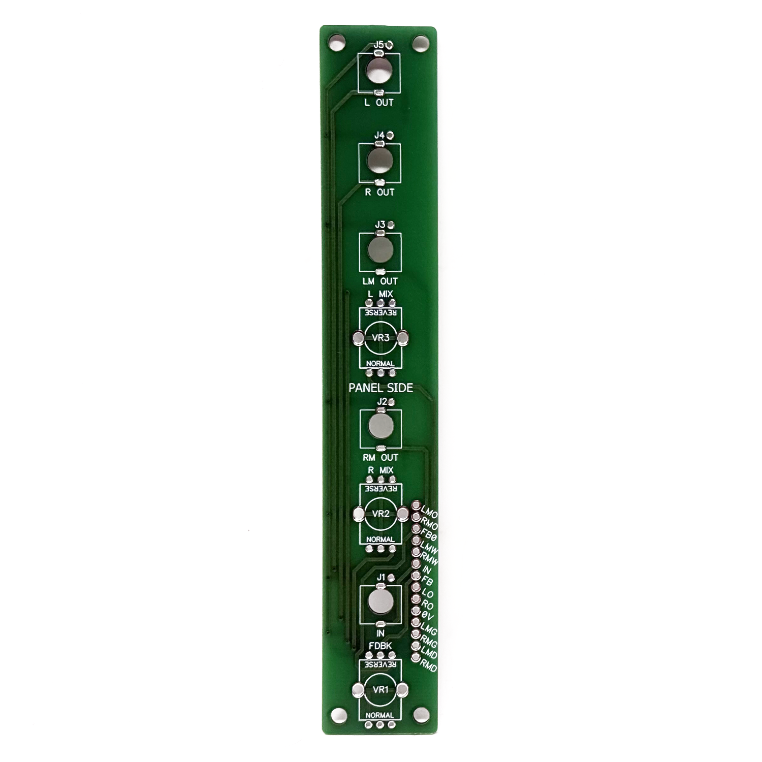 Image 6 of 6
The LGE095 D-Spring Digital Reverb is a recreation of the classic CGS95 Digital Reverb, built around the Belton (Accutronics) BTDR-2 digital reverb module. Designed as a compact alternative to traditional spring tanks, the BTDR-2 delivers a rich, spacious reverb character while occupying only a fraction of the space required by a mechanical spring unit.
From a single audio input, the module generates independent left and right reverb signals, creating a wide stereo image. Dedicated Left Wet and Right Wet outputs provide the processed reverb signal alone, while separate Left Mix and Right Mix controls allow each channel to blend the original dry signal with the reverb independently.
The Feedback control returns a portion of the reverberated signal back into the processor, extending the decay and adding depth to the effect. At higher settings the module can produce lush, evolving ambience or be pushed into self-regenerating feedback for experimental textures.
Faithful to the original CGS95 design, the LGE095 combines the proven BTDR-2 reverb engine with high-quality analog buffering, mixing, and gain stages, making it an excellent addition to any 4U modular synthesizer system.
Front Panel Controls & Connections:
IN - Audio input to the reverb processor.
L WET - Wet-only left reverb output.
R WET - Wet-only right reverb output.
L MIX - Adjusts the balance between the dry input signal and the left reverb output.
R MIX - Adjusts the balance between the dry input signal and the right reverb output.
FDBK - Controls the amount of reverb signal fed back into the processor. Lower settings produce natural decays, while higher settings create longer reverbs and can enter self-regenerating feedback.
Circuit Description:
As previously stated, the LGE095 is based on the classic CGS95 Reverb circuit and uses the Belton (Accutronics) BTDR-2 digital reverb module as its processing engine. The incoming signal is first buffered by U3.1 before passing through a signal conditioning stage consisting of R3, C8, R4, and the Gain trimmer (TR2). This network forms a high-pass filter and gain recovery stage that compensates for the frequency response of the BTDR-2 while setting the drive level into the reverb module.
The cutoff frequency of the input high-pass filter is determined by:
f = 1 / (2π × R3 × C8)
while the high-frequency gain is approximately:
Gain (dB) = 20 × log(R4 / R3)
These values were intentionally left easy to modify, allowing builders to tailor the character of the reverb to their own system and personal taste. There is no single "correct" set of values—the best combination is ultimately the one that sounds best to your ears. Changing C8 or R3 alters the cutoff frequency of the input high-pass filter. Increasing either value lowers the cutoff frequency, allowing more low-frequency content into the reverb for a fuller, warmer sound. Decreasing either value raises the cutoff frequency, reducing bass before it reaches the BTDR-2 and producing a brighter, more traditional spring reverb character. The value of R4 determines the amount of gain recovery following the high-pass filter. Increasing R4 raises the drive level into the BTDR-2, producing a stronger reverb signal but increasing the likelihood of clipping if driven too hard. Reducing R4 decreases the available gain, providing greater headroom and a wider usable adjustment range from the TR2 Gain trimmer.
During development of the LGE095, I found the original CGS values of R4 = 15kΩ with a 20kΩ Gain trimmer (R5) provided considerably more gain than necessary for typical ±5V modular synthesizer signals. With these values, the trimmer needed to be adjusted very near its minimum setting to avoid clipping the input of the BTDR-2, leaving little practical adjustment range.
My recommendation is to begin with the original values and evaluate the module in your own system. If you find, as I did, that the Gain trimmer spends most of its travel near minimum before clipping occurs, consider reducing the value of R4 until the adjustment range better suits your signal levels. There is no universally correct value—the ideal choice depends on the output level of the signals driving the reverb and your own sonic preferences.
One of the strengths of this circuit is how easily it can be tailored. Don't hesitate to experiment with the filter and gain network—small component changes can noticeably alter the overall character of the reverb. If you have the parts on hand, try a few different combinations, trust your ears, and choose the values that best complement your synthesizer and the sounds you want to create. The BTDR-2 generates independent left and right reverb signals, each buffered by dedicated output amplifiers before being presented as Left Wet and Right Wet outputs. Additional active mixer stages combine the original dry signal with each reverb channel, providing independent Left Mix and Right Mix outputs with front-panel wet/dry controls. The Feedback control returns a portion of the reverberated signal back into the input of the BTDR-2, extending the decay from subtle ambience to long sustaining reverberation and experimental self-regenerating feedback. A dedicated 78L05 regulator provides the clean, regulated 5V supply required by the BTDR-2 while the surrounding analog circuitry operates from the system's bipolar supply rails.
PCB Mounting Options:
The LGE095 uses a larger-than-standard main PCB to accommodate the digital reverb circuitry while maintaining a compact single-column front panel. To provide greater flexibility during assembly, the main PCB may be mounted either parallel or perpendicular to the front panel and I/O board using the same PCB set.
The preferred mounting orientation will depend on your modular system. Deeper boats or cabinets can typically accommodate the perpendicular mounting configuration, minimizing the module's horizontal footprint behind the panel. Shallower boats or skiffs may require the parallel mounting configuration, allowing the module to fit comfortably within the available depth.
When assembled in the parallel orientation, the main PCB extends beyond the width of the front panel. Builders may wish to experiment with spacer lengths to provide additional clearance, allowing the PCB to overlap the unused space behind an adjacent module. Another effective approach is to install the LGE095 beside a module that uses only a single PCB mounted parallel to the panel, allowing both modules to share the available space more efficiently.
Ultimately, the mounting orientation is left to the builder or customer to best suit their particular cabinet, boat, or rack configuration. This flexibility was intentionally designed into the module, making it easier to integrate the larger reverb circuitry into a wide variety of 4U modular systems.
Approximate Module Depth:
Parallel PCB: TBD (mm)
Perpendicular PCB: TBD (mm)
Module depths are measured from the rear surface of the front panel to the furthest point on the assembled module. Dimensions are approximate and may vary slightly depending on hardware, spacer length, and assembly method.
LGE095 D-Spring Reverb DIY Information: (Coming soon)
LGE095 Bill of Materials (Contains both Main & I/O Boards)
LGE095 Main Board PCB w/ Designators
LGE095 Main Board Schematic
LGE095C I/O Board Schematic / Wiring Diagram
LGE095C I/O Board PCB w/ Designators
LGE095 Printable Panel Art
Belton BTDR-2 Datasheet
Mechanical Parts BOM generally required for building Low-Gain Electronics Modules
** 4U Modular is a term used for the format most commonly known as “Serge Format” or “Loudest Warning Format”. Out of respect for the ever growing format, 4U Modular is the easiest way to refer to it. More Specifically it refers to the panel height and mounting hole style. 4U Modular will patch up just fine with other 4U "Serge" formats such as "Random Source", but it will not mount in RS boats or Buchla Boats (or power off Buchla power for that matter). An info page about this will be added to the website soon to make this a lot more easy to understand.
Details:
PCB Size: 6” x 1”
Current Draw: TBD