
 Image 1 of 4
 Image 2 of 4
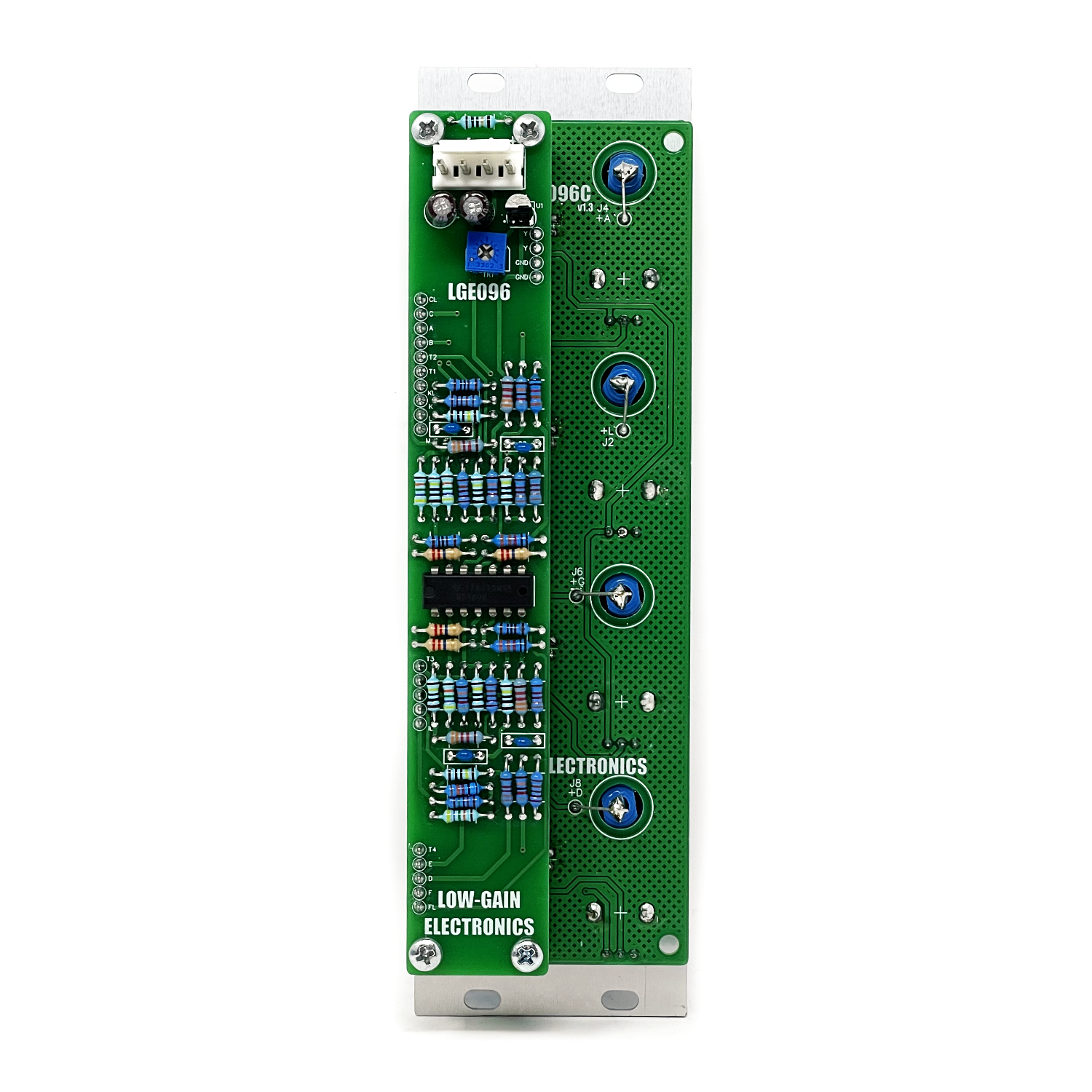 Image 3 of 4
 Image 4 of 4
MODULE DESCRIPTION
The LGE096 Quad Comparator provides four independent voltage comparators based on the classic Serge comparator circuit. Each section includes positive (+) and negative (-) inputs, an adjustable THOLD control, a logic output, and an LED indication of the output state.
A comparator makes a simple decision based on voltage level and produces a high or low output depending on the relationship between its inputs. Within a modular synthesizer, this basic function has a surprisingly wide range of uses. The LGE096 can be used for level detection, gate and pulse generation, waveform squaring, variable pulse-width generation, logic decisions, rhythmic processing, and conversion of continuously varying control or audio signals into discrete switching signals.
The four comparator sections are independent, allowing several unrelated functions to be performed simultaneously or multiple comparators to be combined into more complex patches. The LGE096 expands the Serge comparator concept to four channels while retaining the basic operating principles of the original circuit.
WHAT IS A COMPARATOR?
In electronic terms, a comparator is a circuit that compares voltage levels and changes its output state according to their relationship. Rather than reproducing the shape or amplitude of the input signal, a comparator produces one of two output states: high or low. When the comparison crosses the switching point, the output changes state. This makes a comparator particularly useful in a modular synthesizer because it provides a way of converting continuously varying voltages into events.
For example, an envelope can be converted into a gate that becomes active only after the envelope reaches a selected level. An LFO can generate a pulse whenever its voltage crosses a threshold. An audio waveform can be converted into a rectangular waveform whose transitions correspond to crossings of the comparison level.
The comparison does not need to be against a fixed voltage. Another control voltage or audio signal can be used as part of the comparison, allowing the switching point to change dynamically. This makes comparators useful not only as level detectors, but also as building blocks for pulse-width modulation, rhythmic processing, waveform generation, and voltage-controlled logic.
The original Serge documentation described these applications as "house-keeping functions," but the comparator can just as easily become an active part of a patch or even a sound source.
PANEL / OPERATION
Each of the four sections of the LGE096 contains the following controls and connections.
+ IN : Positive comparator input.
Signals applied here are compared against the voltage present at the negative side of the comparator and the manually adjustable threshold reference.This input can accept control voltages, envelopes, LFOs, sequencer voltages, audio signals, or other continuously varying voltages.
- IN : Negative comparator input.
This input allows an external voltage to participate in the comparison rather than relying only on the manually selected threshold. Patching another control or audio signal here allows the comparison point to change dynamically and makes possible more complex voltage-controlled switching, pulse-width, and logic functions.
THOLD : Manually adjusts the comparator's threshold reference.
The control operates from the module's internal +6V reference and provides a convenient way to establish a fixed comparison level without requiring an external control voltage. At its minimum setting, the comparator can be used for detecting crossings near 0V. Increasing THOLD raises the manually established comparison level.The THOLD control can therefore determine when an envelope or other control voltage produces an output, or alter the duty cycle of a periodic waveform being converted into pulses.
OUT : Comparator output.
The output switches between low and high states according to the relationship between the comparator inputs and threshold. The output can be used anywhere a gate, pulse, logic, clock, or other switching signal is required.
LED : The LED indicates the current state of the comparator output.
This is useful both during normal operation and when using the module for slowly changing control voltages or during calibration.
CIRCUIT DESCRIPTION
The LGE096 Quad Comparator is based on the classic Serge comparator circuit, expanded to provide four independent comparator sections. Each comparator uses a section of an LM3900 quad Norton amplifier along with the associated input, threshold, feedback, and output networks. The circuit compares the voltages presented at its positive and negative inputs against the manually adjustable threshold reference and switches its output between low and high states according to their relationship.
The four THOLD controls operate from a common regulated +6V reference generated locally on the module. This provides a stable reference for manually setting the comparison point of each channel. Each comparator output includes a series output resistor and a dedicated LED indicator, providing both a usable logic-level output and visual indication of the comparator's current state. A single calibration adjustment establishes the common operating point of the comparator circuitry. Once calibrated, a bipolar waveform centered around 0V will produce an approximately symmetrical output with the THOLD control at its minimum setting.
Although the comparator can process both control voltages and audio-rate signals, its output is a switching waveform rather than a linear reproduction of the input. This allows continuously varying signals to be converted into gates, pulses, rectangular audio waveforms, and logic signals. The basic circuit originates from the Serge comparator designs of the 1970s and retains the characteristic flexibility of using both fixed and voltage-variable comparison levels.
COMMON PATCH IDEAS
LEVEL DETECTOR
Patch an envelope, LFO, sequencer voltage, or other control signal into the + IN. Use THOLD to select the voltage level at which the comparator changes state. The OUT jack will produce a high or low signal depending on whether the incoming voltage is above or below the selected threshold. This can be used to generate gates or other logic signals from continuously varying control voltages. For example, an envelope follower can be used with the comparator to generate a gate whenever an audio signal exceeds a selected amplitude.
ENVELOPE EVENT GENERATOR
Patch an envelope into + IN and adjust THOLD to a point within the envelope's voltage range. The comparator changes state as the envelope crosses the selected threshold. Moving THOLD changes the point during the envelope at which the transition occurs. This can be used to initiate another event at a particular point during an envelope's rise or fall.
SQUARING AN AUDIO SIGNAL
Patch an audio waveform into + IN and set THOLD near minimum.
The comparator converts the incoming waveform into a rectangular waveform by switching states as the input crosses the comparison point. Sine, triangle, sawtooth, and more complex signals can therefore be converted into pulse-like waveforms. The resulting signal can be used directly as audio or as a source of frequency-related pulses for other modules.
VARIABLE PULSE WIDTH
Patch a triangle or sawtooth oscillator waveform into + IN and monitor OUT. Adjusting THOLD changes the point during each cycle at which the comparator switches. This changes the proportion of the cycle for which the output remains high, producing a variable-width rectangular waveform. At audio frequencies, this provides manual pulse-width control and produces a harmonically rich waveform derived from the original oscillator.
VOLTAGE-CONTROLLED PULSE WIDTH
Patch a triangle or sawtooth oscillator into one comparator input and a changing control voltage into the opposing input. The external control voltage moves the comparison point dynamically, changing the width of the resulting pulse waveform. LFOs, envelopes, sequencers, or other modulation sources can be used to create continuously changing pulse widths and more complex waveform shapes.
COMPARE TWO CONTROL VOLTAGES
Patch two different control voltages into + IN and - IN. The comparator output changes state according to the relationship between the two signals. This allows one control voltage to make a logical decision based on the level of another. For example, two LFOs running at different frequencies can generate a repeating but complex gate pattern as their waveforms cross one another.
RHYTHMIC PULSE GENERATION
Patch an LFO, sequencer voltage, stepped random voltage, envelope, or other repeating control signal into the comparator. Adjust THOLD to select which portions of the incoming signal produce a high output. With more complex modulation sources, small changes to THOLD can significantly alter the resulting rhythmic pattern without changing the source signal itself.
MULTIPLE THRESHOLD DETECTION
Patch the same control voltage into the + IN of two or more comparator sections and set each THOLD control to a different position. Each comparator will change state at a different voltage level, allowing several related gates or switching signals to be derived from a single control voltage. For example, a slowly rising envelope or ramp can produce a sequence of events as it passes through the different thresholds established by the four comparator sections.
CALIBRATION
The LGE096 contains a single calibration trimmer that establishes the operating point of the comparator circuitry. Calibration is best performed with an oscilloscope and a bipolar triangle wave centered around 0V.
OSCILLOSCOPE METHOD
Allow the module to power up normally before calibration.
Set the THOLD control of the comparator being tested fully counterclockwise.
Apply a symmetrical bipolar triangle wave centered around 0V to the comparator input.
Monitor the corresponding OUT jack with an oscilloscope.
Observe the rectangular waveform at the output.
Adjust the calibration trimmer until the output has approximately a 50% duty cycle.
With THOLD at minimum, a properly calibrated comparator should change state at approximately the midpoint of a symmetrical bipolar triangle waveform.
After calibration, the remaining comparator sections can be checked in the same manner to verify proper operation.
CALIBRATION WITHOUT AN OSCILLOSCOPE
An approximate calibration can also be performed using the panel LED.Use a very slow bipolar triangle wave centered around 0V and set THOLD fully counterclockwise.
Patch the triangle wave into the comparator input and watch the corresponding output LED. Adjust the calibration trimmer until the LED spends approximately equal amounts of time ON and OFF during each cycle. This method is less precise than using an oscilloscope but provides a simple way to establish the comparator's operating point when test equipment is limited.
HISTORICAL NOTES
Voltage comparators have been part of the Serge modular system since the early years of Serge Modular Music Systems and were used as general-purpose building blocks for both control and audio processing. The Serge Comparator was intended for several functions that Serge described as useful "house-keeping" duties within a modular system. These included logical decisions based on voltage levels, level detection, voltage-variable pulse-width modulation, and "squaring" audio signals to produce frequency-related pulses. The comparator's ability to use either a manually established threshold or another changing voltage as part of the comparison makes the circuit considerably more flexible than a simple gate detector. It can operate as a utility, logic element, waveform processor, rhythmic generator, or audio-rate synthesis tool depending on how it is patched.
The LGE096 Quad Comparator builds on this classic Serge concept by providing four independent comparator sections in a single module.
LGE096 Quad Comparator DIY Build Info:
LGE096 Main Board Bill of Materials
LGE096 Main Board Schematic
LGE096 Main Board Layout w/ Designators
LGE096 I/O Board Schematic (Wiring Diagram)
LGE096 I/O Board Bill of Materials
LGE096 I/O Board Layout w/ Designers
Mechanical Parts BOM generally required for building Low-Gain Electronics Modules
Details:
PCB Size: 6” x 2”
Current Draw: TBD
** 4U Modular is a term used for the format most commonly known as “Serge Format” or “Loudest Warning Format”. Out of respect for the ever growing format, 4U Modular is the easiest way to refer to it. More Specifically it refers to the panel height and mounting hole style. 4U Modular will patch up just fine with other 4U "Serge" formats such as "Random Source", but it will not mount in RS boats or Buchla Boats (or power off Buchla power for that matter). An info page about this will be added to the website soon to make this a lot more easy to understand.