
 Image 1 of 4
 Image 2 of 4
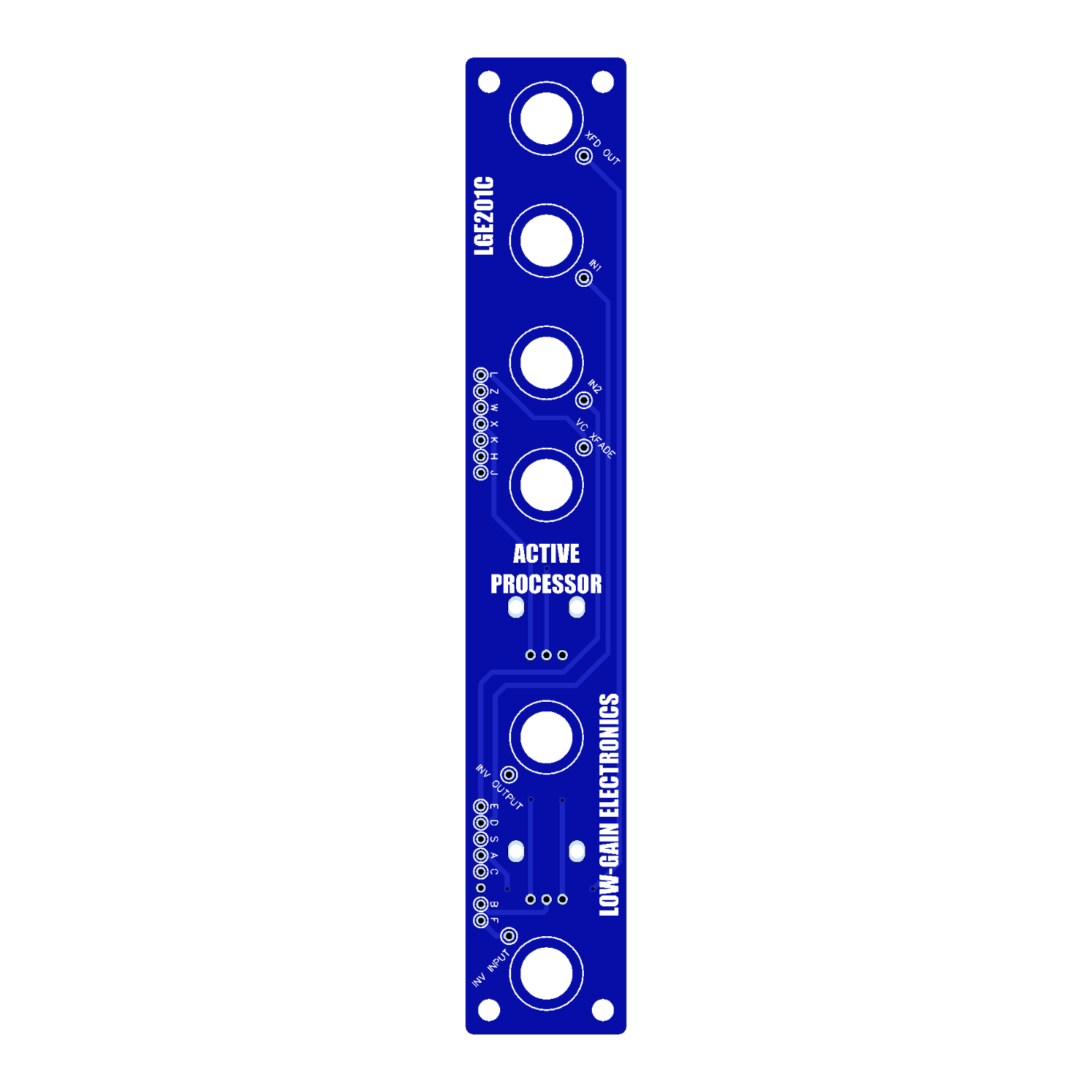 Image 3 of 4
 Image 4 of 4
LGE201 Active Processor
The LGE201 Active Processor (ACPR) is a precision analog signal processor that combines a voltage-controlled linear crossfader with an active scaling and inversion stage. Designed for both control voltages and audio signals, it provides smooth, accurate signal blending and flexible voltage processing, making it an invaluable utility in any modular synthesizer system.
At the heart of the module is a true linear crossfader that continuously blends between Input 1 and Input 2. The fade position can be adjusted manually with the XFade control or modulated externally via the VC XFade input, allowing dynamic transitions under envelope, LFO, sequencer, or other control voltage modulation. Because the crossfade is linear and DC-coupled, it performs equally well with audio and CV signals.
The lower section functions as an active processor and scaling buffer. An incoming signal is inverted and can be offset using the front-panel Offset control, making it ideal for creating inverted modulation sources, shifting voltage ranges, or generating complementary control signals. As an active circuit, it maintains signal integrity while providing accurate voltage processing without the loading effects common to passive processors.
Whether you're morphing between modulation sources, fading between audio signals, creating evolving control voltages, or generating inverted and offset versions of existing signals, the Active Processor is one of those indispensable utility modules that quickly becomes a central part of patching.
Front Panel Controls & Connections
Upper Section – Voltage-Controlled Crossfader
Input 1 – First audio or control voltage input.
Input 2 – Second audio or control voltage input.
VC XFade – External control voltage input for voltage-controlled crossfading.
XFade – Manual control that blends smoothly between Input 1 and Input 2.
Output – Crossfaded output signal.
Lower Section – Active Processor
INV IN – Signal input to the processor.
Offset – Adds adjustable positive or negative DC offset to the processed signal.
Output – Inverted and offset processed signal.
LGE201 Active Processor DIY Information:
LGE201 Bill of Materials (Contains both Main & I/O Boards)
LGE201 Main PCB Schematic
LGE201 Main PCB Designators
LGE201C I/O PCB Schematic
LGE201C I/O PCB Designators
LGE201 Panel Art
Mechanical Parts BOM generally required for building Low-Gain Electronics Modules
LGE201 Active Processor / LGE201P Pan/Fade – Calibration Procedure
The LGE201 Active Processor (or LGE201P Pan/Fade) is built around two OTA-based VCAs (CA3280). Each VCA has multiple trimmers for calibration.
TR1 – Output Offset (VCA 1)
TR2 – Output Offset (VCA 2)
TR3 – Linearization Bias / Offset (CA3280)
TR4 – VC Gain (VCA 2)
TR5 – VC Gain (VCA 1)
1. Output Offset Calibration
Leave all inputs unpatched.
Set the X-Fade control fully CCW (Input 1).
Measure the output with a voltmeter or oscilloscope.
Adjust TR1 until the output reads as close to 0 V as possible.
Alternate method (no meter/scope): Patch the output to a VCO’s 1V/Oct input. Adjust TR1 so that plugging/unplugging the Active Processor output produces no pitch shift.
Repeat the above steps for VCA 2 by turning the X-Fade fully CW (Input 2) and adjusting TR2.
2. Linearization Calibration
Keep all inputs unpatched.
Measure the output offset again.
Adjust TR3 for as close to 0 V at the output as possible.
Recheck and fine-tune TR1 and TR2 if needed.
Note: This trimmer sets the CA3280’s linearization bias. For deeper technical detail, see the CA3280 datasheet.
3. VCA Gain Calibration
Patch a 1 kHz sine wave into Input 1.
Set X-Fade fully CCW (Input 1).
Measure the output with an oscilloscope.
Adjust TR5 so the output amplitude matches the input amplitude.
Example: If the input is ±5 V, adjust until the output is also ±5 V.
Repeat for VCA 2:
Move the test signal to Input 2.
Set X-Fade fully CW (Input 2).
Adjust TR4 until the output matches the input.
Notes on Operation
When the manual X-Fade control is fully CW (VCA 2), applying CV to the X-Fade CV input will boost VCA 2’s signal. This happens because both the manual bias and CV are summed at VCA 2’s control input.
To achieve equal levels when mixing two signals of the same range:
Set X-Fade control fully CCW.
Turn the X-Fade CV attenuator fully CW.
Calibration complete – your LGE201 Active Processor should now operate with balanced offsets and gains.
Details:
1 Column
PCB Size: 6” x 1”
Current Draw: TBD
** 4U Modular is a term used for the format most commonly known as “Serge Format” or “Loudest Warning Format”. Out of respect for the ever growing format, 4U Modular is the easiest way to refer to it. More Specifically it refers to the panel height and mounting hole style. 4U Modular will patch up just fine with other 4U "Serge" formats such as "Random Source", but it will not mount in RS boats or Buchla Boats (or power off Buchla power for that matter). An info page about this will be added to the website soon to make this a lot more easy to understand.