
 Image 1 of 8
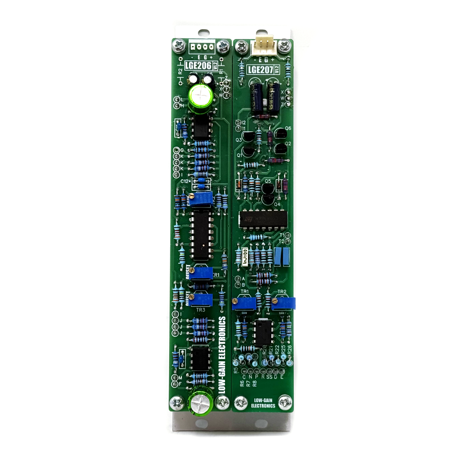 Image 2 of 8
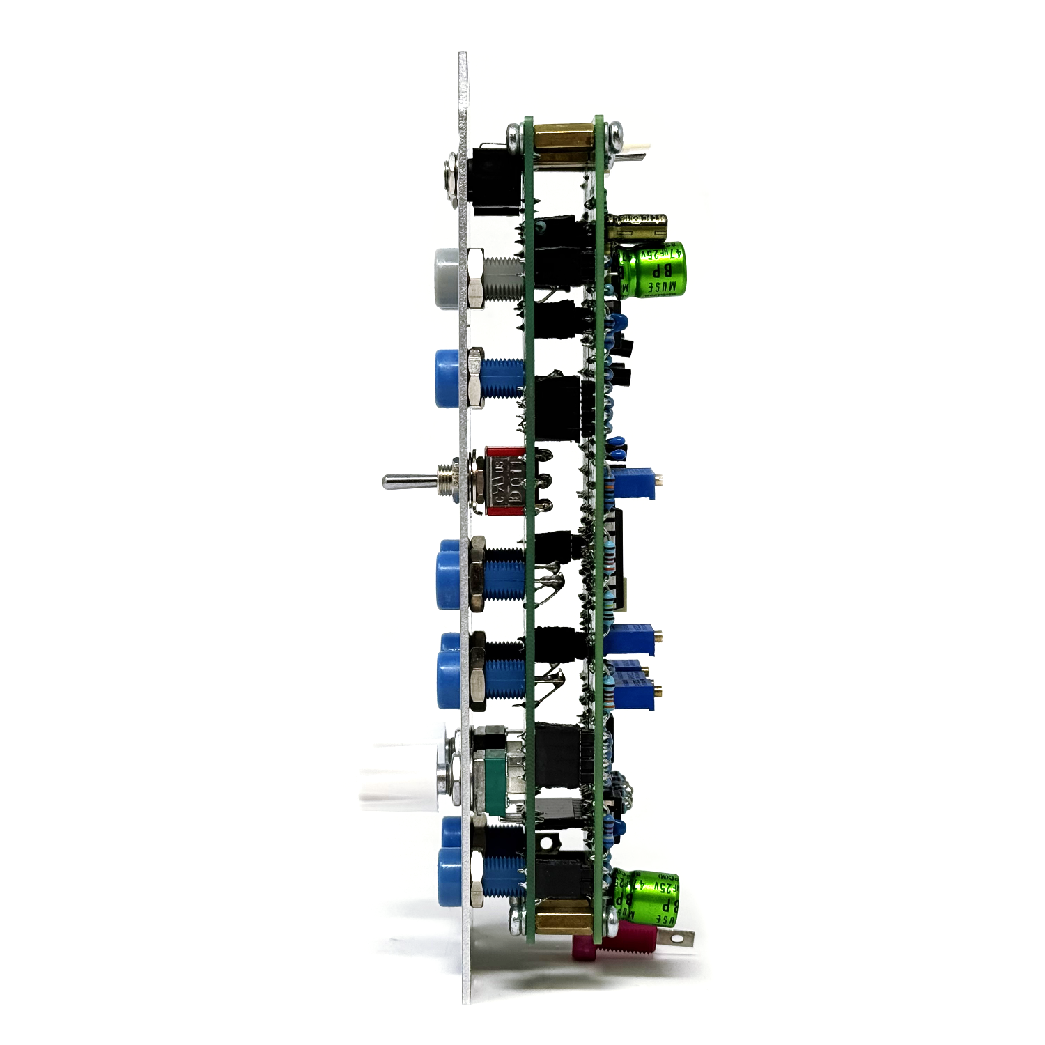 Image 3 of 8
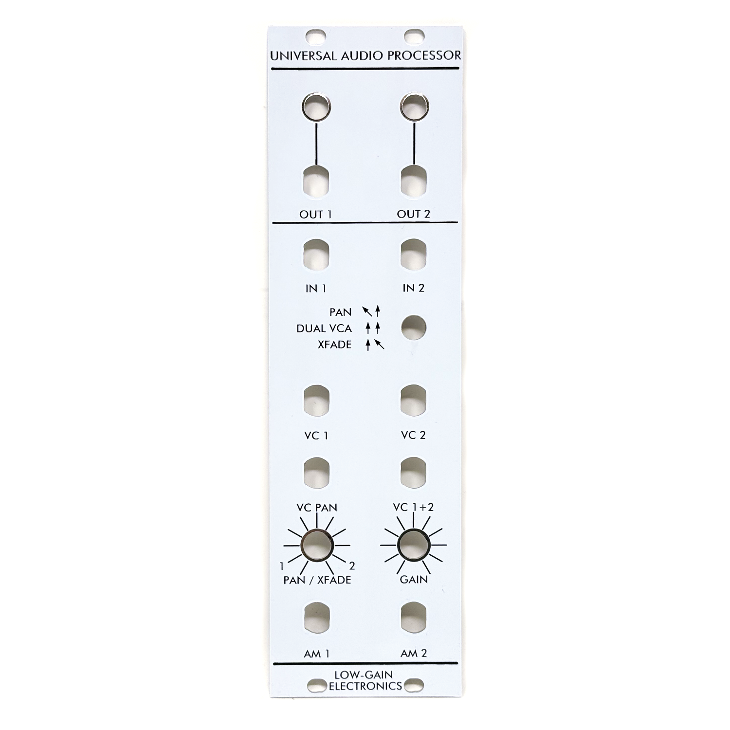 Image 4 of 8
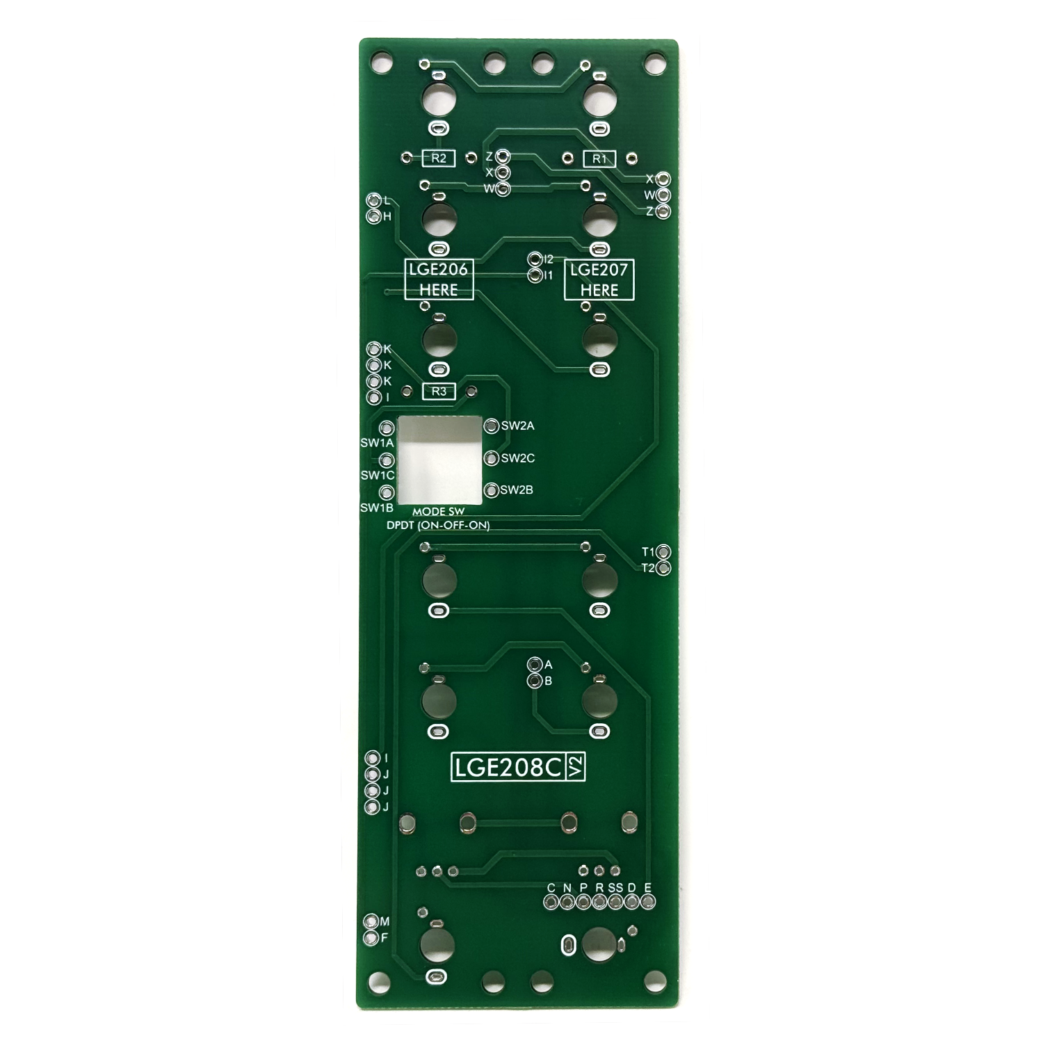 Image 5 of 8
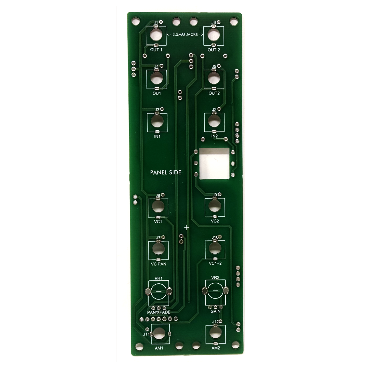 Image 6 of 8
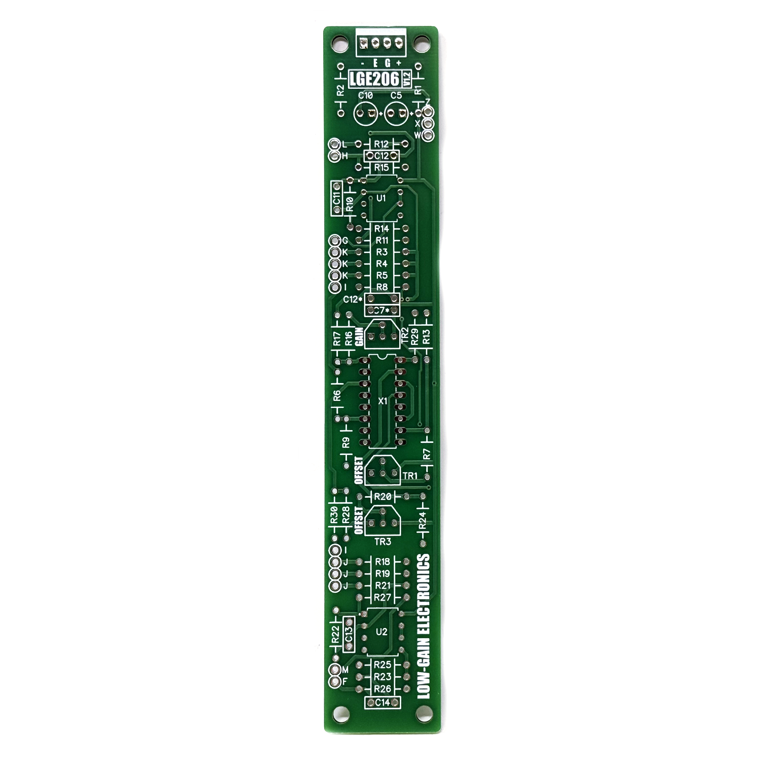 Image 7 of 8
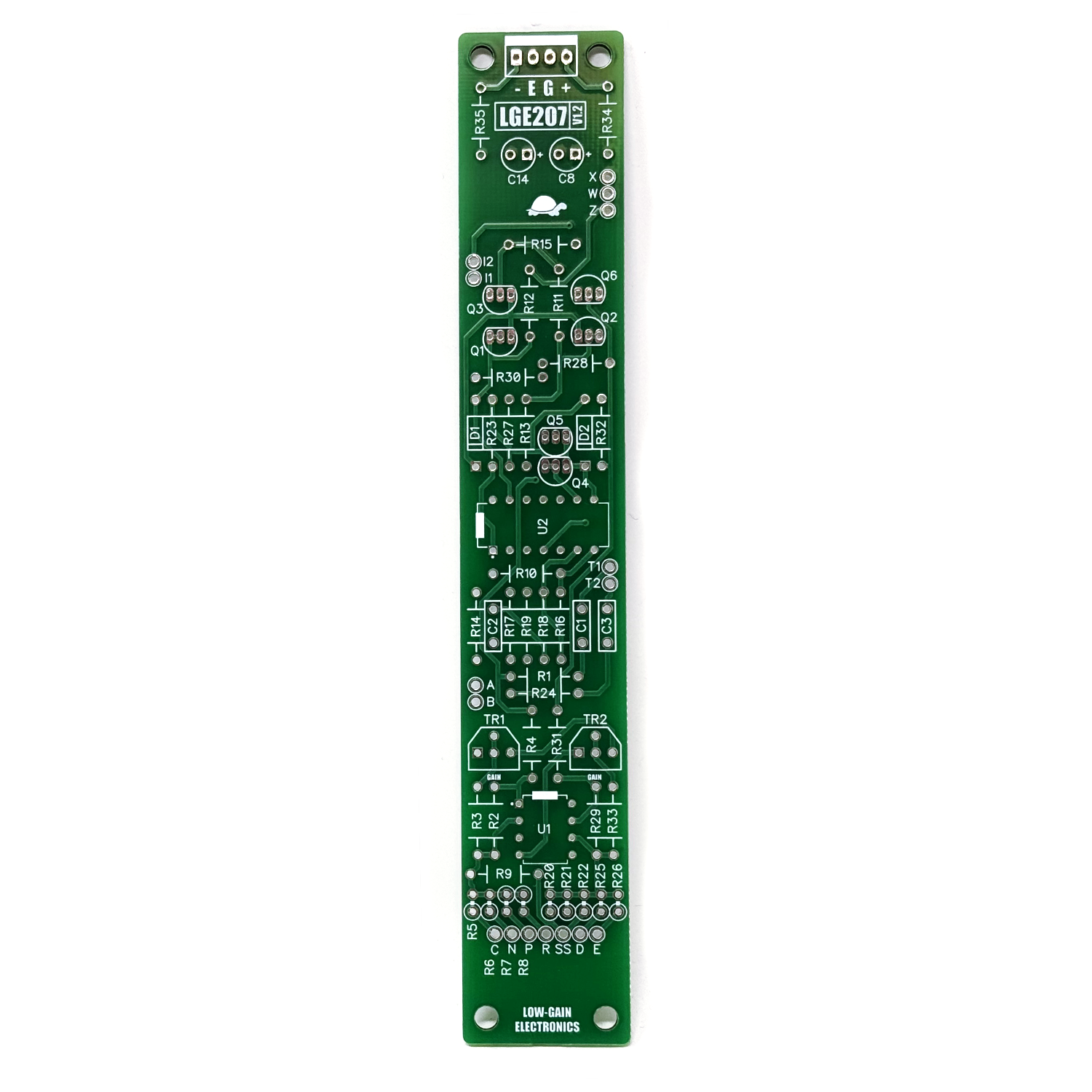 Image 8 of 8
LGE208 Universal Audio Processor
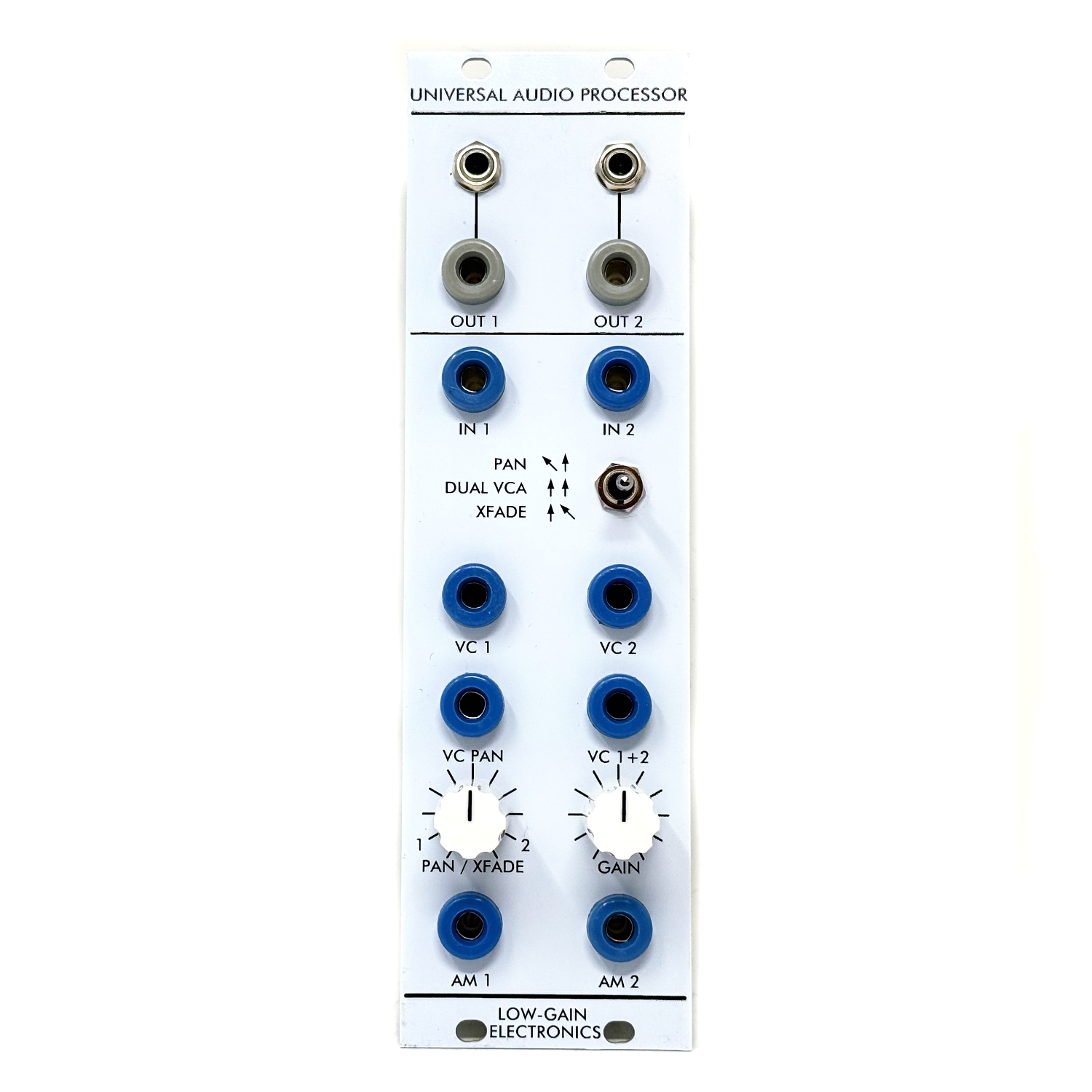
The Low-gain Electronics LGE208 Universal Audio Processor (UAP) is a versatile, dual-channel voltage-controlled audio processor based on the original Serge Modular design. Combining two voltage-controlled amplifiers with an equal-power control circuit, the UAP provides three distinct operating configurations: Dual VCA, Stereo Panner, and Voltage-Controlled Crossfader. Originally conceived as a multifunctional audio processor for smaller Serge systems, the UAP offers a flexible approach to amplitude control, stereo positioning, and dynamic signal routing within a single module.
Dual VCA Mode provides two independent voltage-controlled amplifiers, each with dedicated audio inputs, outputs, and control voltage inputs. This configuration is useful for traditional amplitude modulation, envelope-controlled dynamics, and independent signal processing.
Stereo Panner Mode distributes a single audio signal between two outputs using an equal-power panning response. Manual and voltage-controlled panning allow sounds to move dynamically across the stereo field, while additional amplitude controls provide control over the overall signal level.
Crossfader Mode allows two independent audio signals to be blended under voltage control. As the level of one signal increases, the other decreases, making it useful for transitioning between sound sources, creating evolving timbres, and voltage-controlled signal routing. The UAP's combination of amplitude processing, panning, and crossfading makes it equally useful for conventional audio mixing and more experimental applications within a Serge Modular system. The LGE208 is designed for 4U Serge-compatible modular synthesizers and is constructed from three interconnected circuit boards: the LGE206 Dual VCA, LGE207 Stereo Equal Power Driver, and LGE208 I/O board.
Circuit Description
The LGE208 Universal Audio Processor consists of three interconnected printed circuit boards that work together to provide voltage-controlled amplitude processing, stereo panning, and crossfading.
LGE206 Dual VCA
The LGE206 contains two independent voltage-controlled amplifier circuits responsible for processing the module's audio signals. Each VCA utilizes an operational transconductance amplifier (OTA) to control signal amplitude in response to an applied control current. The audio inputs are AC-coupled and buffered before entering the VCA circuitry, while additional operational amplifiers provide output signal conditioning. Individual offset and gain adjustments allow the two VCA circuits to be calibrated for consistent performance. The LGE206 receives its control currents from the LGE207, allowing the two amplifiers to operate independently or together for panning and crossfading applications.
LGE207 Stereo Equal Power Driver
The LGE207 provides the control circuitry responsible for generating the complementary VCA control currents used for stereo panning and crossfading. The circuit combines manual control voltages, external control voltage inputs, and adjustable offset references to establish the operating levels of the two VCAs. Operational amplifiers and transistor-based current-driving stages convert these control signals into the control currents required by the LGE206. In panning and crossfading configurations, the control circuitry produces complementary amplitude responses, allowing the relative levels of the two VCA channels to change together. The circuit also provides control over the overall amplitude of the processed signals, allowing independent gain control alongside the panning or crossfading function.
LGE208 I/O Board
The LGE208 I/O board provides the interface between the front panel and the LGE206 and LGE207 circuit boards.It accommodates the audio inputs and outputs, control voltage connections, manual controls, and the three-position operating mode switch.The mode switch changes the signal routing between the two VCA channels, allowing the module to function as a Dual VCA, Stereo Panner, or Voltage-Controlled Crossfader without requiring external patching between the two circuits. The I/O board also provides the connections for the manual PAN/XFADE and GAIN controls, as well as the individual and combined voltage-control inputs.Together, the three circuit boards form a flexible audio-processing system capable of independent amplitude control, voltage-controlled stereo positioning, and dynamic blending between audio sources.
Panel Functions
Audio Inputs
IN 1 / IN 2
Audio signal inputs for the two VCA channels. Their routing depends on the selected operating mode.
Audio Outputs
OUT 1 / OUT 2
Individual audio outputs for the two VCA channels. In panning mode, these function as the two stereo outputs. These are modular level.
1/8" Output Jacks
Additional output connections for OUT 1 and OUT 2, allowing connection to external audio equipment. These are closer to line level. Right angle 1/8” male to 1/4” female adapter cables recommended
Operating Mode Switch
PAN / DUAL VCA / XFADE
Three-position toggle switch selecting the module's operating configuration.
PAN (Up): Routes a single audio input to both VCA channels for stereo panning.
DUAL VCA (Center): Configures the two VCAs for independent operation.
XFADE (Down): Configures the two audio channels for voltage-controlled crossfading.
Control Voltage Inputs
VC 1 / VC 2: Individual voltage-control inputs for the two VCA channels.
VC PAN: External voltage-control input for the panning or crossfading position.
VC 1+2: Common voltage-control input affecting the gain of both VCA channels.
Manual Controls
PAN / XFADE: Manual control for setting the balance between the two VCA channels during panning or crossfading operation.
GAIN: Manual gain control affecting the overall amplitude of both VCA channels.
Amplitude Modulation Inputs
AM 1 / AM 2: AC-coupled amplitude modulation inputs for the individual VCA channels. These inputs allow audio-rate and other changing modulation signals to influence the amplitude of their respective channels independently of the DC-coupled voltage-control inputs.
Operating Modes
Dual VCA
With the mode switch in the center position, the module operates as two independent voltage-controlled amplifiers.
Audio signals connected to IN 1 and IN 2 are processed separately and appear at their respective outputs.
The individual control voltage inputs provide independent amplitude control, making this mode useful for envelope-controlled signals, modulation, and general-purpose voltage-controlled amplitude processing.
Stereo Panner
With the mode switch in the upper position, a single audio signal is distributed between the two VCA channels.
The PAN/XFADE control determines the relative signal levels at OUT 1 and OUT 2, while the VC PAN input allows the panning position to be controlled by external modulation sources such as LFOs, envelopes, or sequencers.
The equal-power control circuit is designed to maintain a more consistent perceived loudness as the signal moves between the two outputs.
The GAIN control and VC 1+2 input provide additional control over the overall amplitude.
Voltage-Controlled Crossfader
With the mode switch in the lower position, the module operates as a voltage-controlled crossfader between two audio signals.
The PAN/XFADE control determines the relative contribution of the two inputs, while external control voltages allow the balance to be modulated dynamically.
Crossfading can be used to transition between different waveforms, alternate sound sources, or create evolving timbres by blending two independently generated signals.
The module's gain controls provide additional amplitude control over the processed signals.
Universal Audio Processor Build Notes / Calibration: Coming soon
LGE206 Dual VCA DIY Build Documentation:
LGE206 Main Board Bill of Materials
LGE206 Main Board Schematic
LGE206 Main Board Designator Layout
LGE207 Stereo Equal Power Driver DIY Build Documentation:
LGE207 Main Board Bill of Materials
LGE207 Main Board Schematic
LGE207 Main Board Designator Layout
LGE208 Universal Audio Processor I/O Board DIY Build Documentation:
LGE208 Bill of Materials
LGE208 Panel Art
Mechanical Parts BOM generally required for building Low-Gain Electronics Modules
Serge Modular Ecosystem Compatibility
Modern Serge-style 4U systems use two primary mounting standards: Loudest Warning–style and Random*Source–style.
Low-gain Electronics modules follow the Loudest Warning–style mounting format (unless stated otherwise) and are electrically
compatible with all Serge-style systems, though mounting (panels) and power adapters may be required for some installations.
Please contact us if you have further questions about this.