
 Image 1 of 5
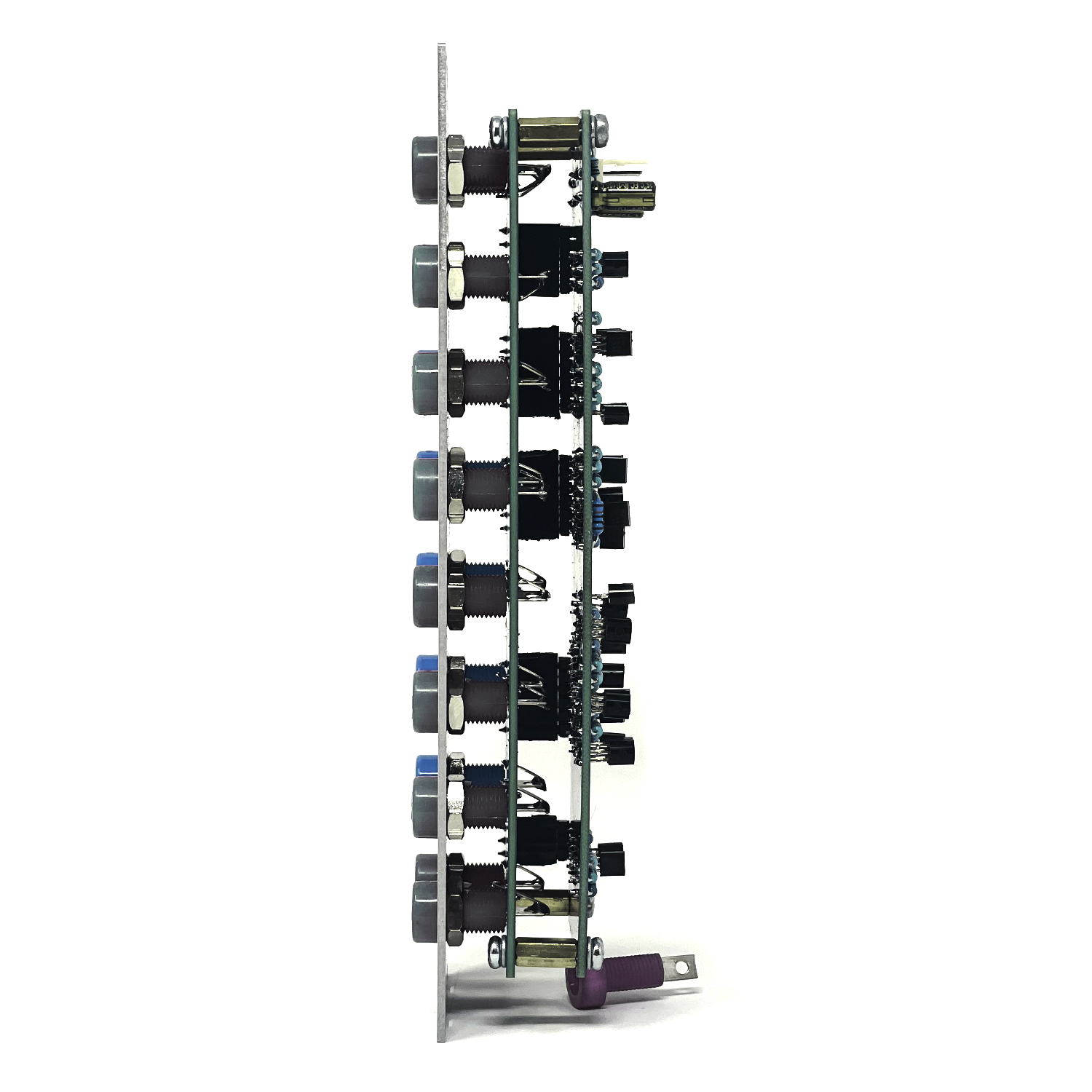 Image 2 of 5
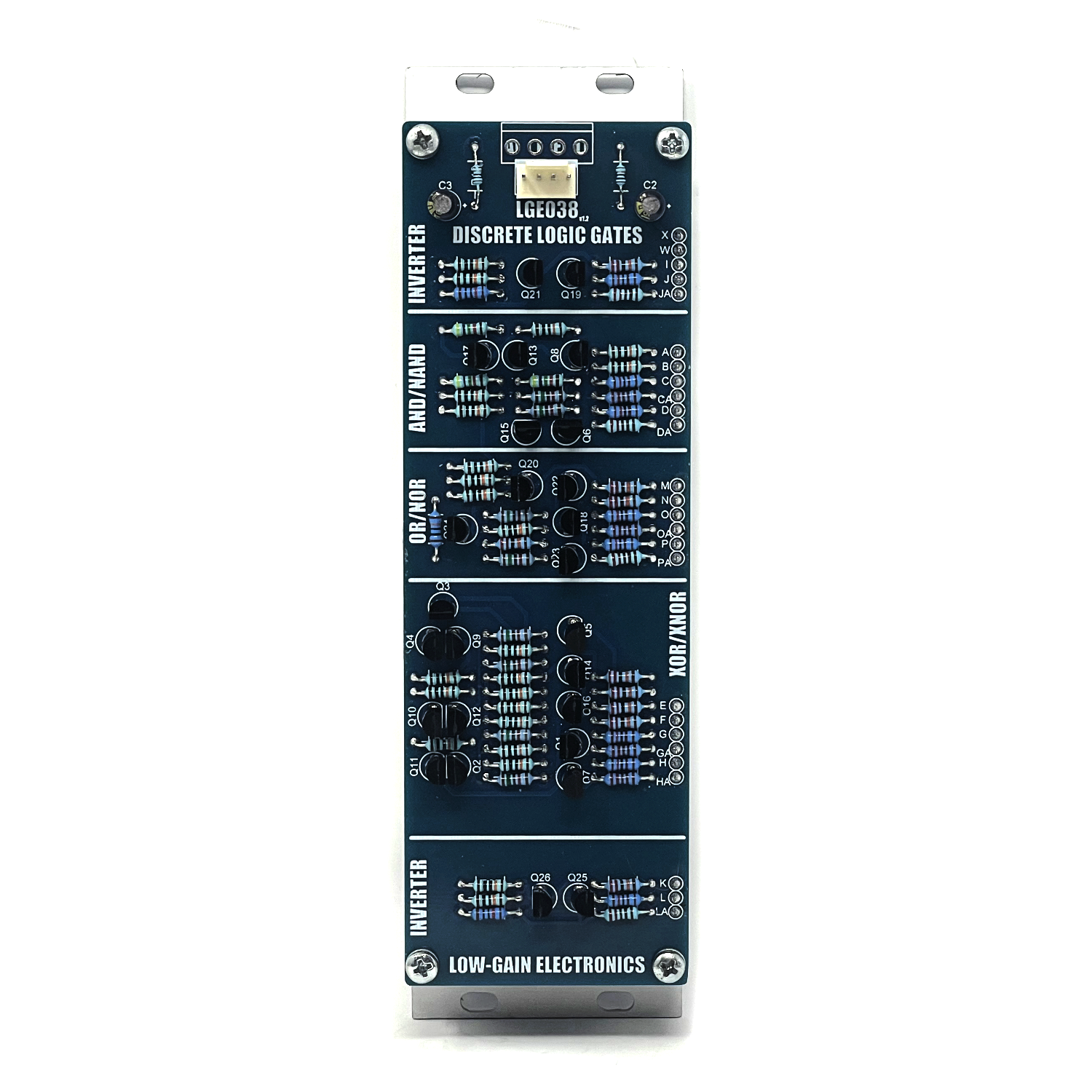 Image 3 of 5
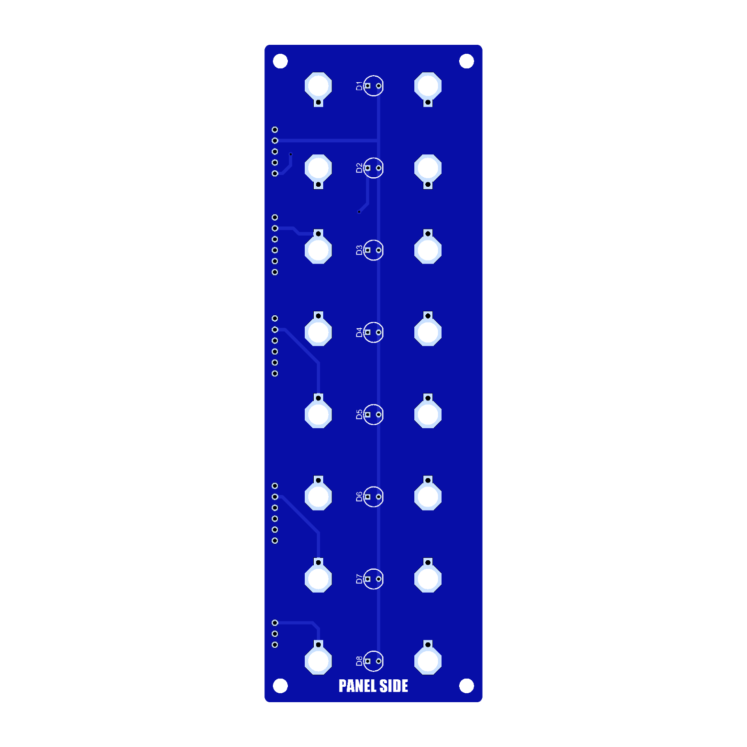 Image 4 of 5
 Image 5 of 5
The LGE038 Discrete Logic brings together six of the most useful logic functions—AND, NAND, OR, NOR, XOR, and XNOR—along with two dedicated inverters. Built entirely from discrete transistors instead of logic ICs, the module provides a collection of fundamental logic tools for processing gates, triggers, clocks, control voltages, and even audio-rate signals.
Whether you're combining clock sources, generating complex trigger patterns, comparing rhythmic events, or experimenting with audio-rate logic, the Discrete Logic makes it easy to build more sophisticated patches from simple signals.
Panel Overview: The module is arranged in four independent processing sections, each designed for quick, intuitive patching.
Inverters
Located at the top and bottom of the panel, the two inverter sections provide simple NOT logic. A high input becomes low, and a low input becomes high.
Inverters are useful for creating complementary gate signals, generating off-beat rhythms, or producing opposite responses elsewhere in a patch.
AND / NAND
This section contains both the AND and NAND functions from a shared pair of inputs.
AND outputs a gate only when both inputs are high.
NAND is the exact opposite, remaining high unless both inputs are active.
These functions are ideal for conditional sequencing, combining clocks, or creating patches where one event depends on another.
OR / NOR
The OR and NOR section also shares a common pair of inputs.
OR outputs a gate whenever either input is active.
NOR outputs a gate only when neither input is active.
These are excellent for merging trigger sources or creating logic based on the absence of activity.
XOR / XNOR
The final logic pair compares two incoming signals.
XOR produces an output whenever the inputs differ.
XNOR produces an output whenever both inputs are the same.
These gates are particularly useful for generating evolving rhythms from multiple clocks, comparing pulse trains, or producing unusual textures when driven with audio-rate signals.
Visual Feedback
Each logic output includes its own LED indicator, allowing the current logic state to be monitored at a glance. This makes it easy to understand what's happening in complex patches and simplifies troubleshooting during performance.
Patch Ideas: The Discrete Logic is equally at home as a utility module or a creative sound design tool.
Common applications include:
Combining multiple clock sources
Building conditional trigger patterns
Creating rhythmic fills and variations
Comparing sequencer outputs
Inverting envelopes and gate signals
Audio-rate logic processing for aggressive digital-style timbres
Constructing larger logic networks by patching multiple sections together
A Note About the Design:
Unlike most modern logic modules, which rely on CMOS logic ICs, every logic function in the LGE038 is built from individual transistors. The result is a classic, fully discrete implementation of the fundamental logic gates that feels right at home in a Serge system. While it performs familiar digital logic operations, the analog nature of the circuitry also encourages experimentation with signals beyond simple gates and triggers.
LGE038 DIY Build Information: V1 pcb building… there is a board error where one leg of Q17 isn’t grounded and leaves AND output at a Logic HIGH.. To fix this, simply run a jumper or scratch the mask off the ground plane and connect Pin 1 to ground.
LGE038 Bill of Materials (Contains both Main & I/O Boards)
LGE038 Main Board Schematic_V1.0
LGE038 Main Board V1.0 AND/NAND Output Modification
LGE038 Main Board Schematic V1.1 (Board not available yet, but shows the error on the V1.0 PCB)
LGE038 Main Board Designator Layout
LGE038C I/O Board Designator Layout
LGE038C Main Board Schematic / Wiring Diagram
Mechanical Parts BOM generally required for building Low-Gain Electronics Modules
Details:
PCB Size: 6” x 2”
Current Draw: TBD