
 Image 1 of 4
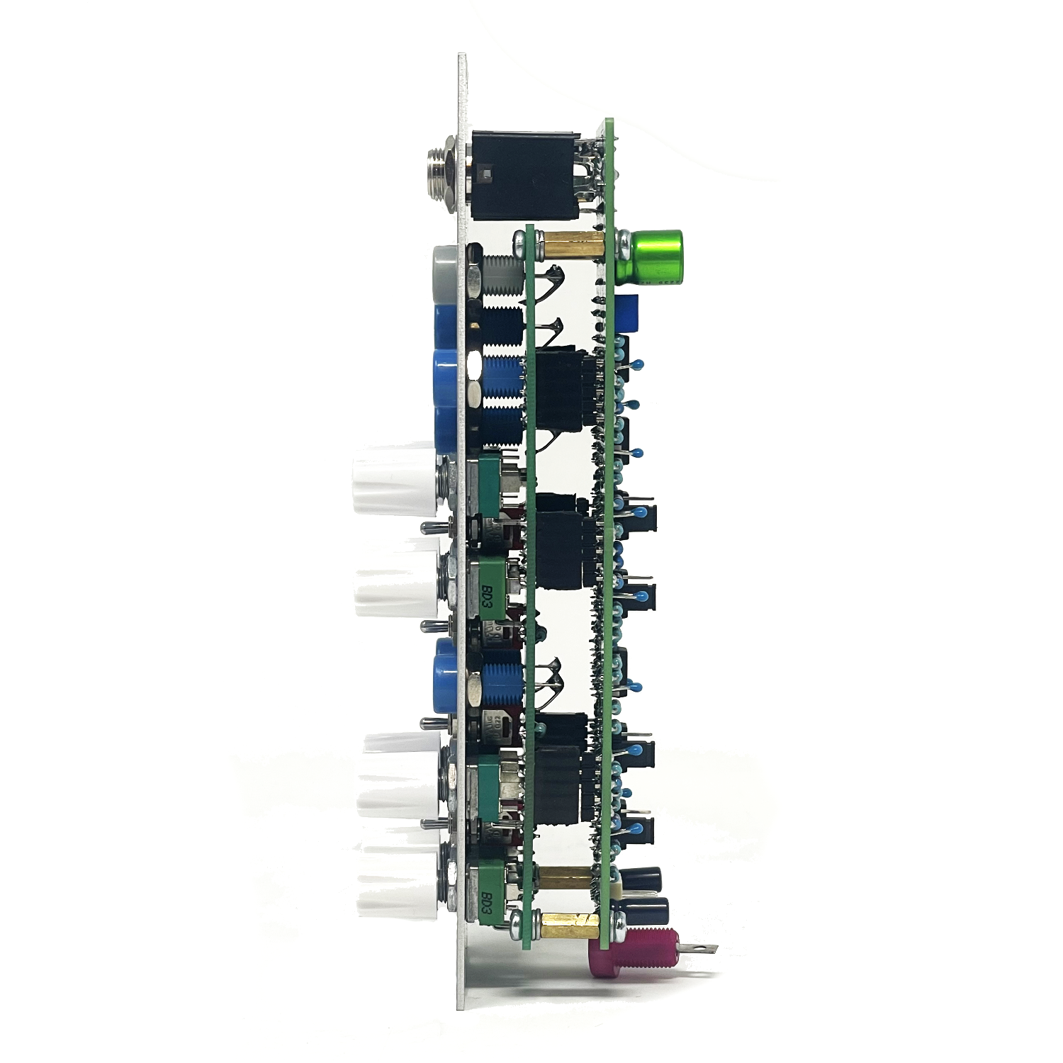 Image 2 of 4
 Image 3 of 4
 Image 4 of 4
A compact stereo mixing solution designed for 4U modular systems, the Pots’n’Pans delivers flexible routing, voltage-friendly outputs, and seamless expansion in a tight 2-column format. Whether used as a final output stage or a submixer within a larger patch, it provides precise control over level, polarity, and stereo placement.
Overview
The Pots’n’Pans features four primary input channels with level control, pan positioning, and signal conditioning. Each channel is optimized for both audio and control voltage use, making it equally at home as a performance mixer or utility processor.
Input Channels (1–4)
Level Control (Attenuation)
Each input includes an attenuator for setting signal level into the mix.Gain Configuration (Rear Jumper)
Per-channel jumper selects:x1 (unity gain)
x2 (boost for lower-level signals)
Pan Control
Positions the signal within the stereo field between left and right mix buses.On / Cut / Invert Switch
On: Signal passes normally into the mix
Cut: Channel is muted
Invert: Signal polarity is inverted before entering the mix bus
Useful for phase cancellation, stereo width tricks, and CV inversion.
Aux Inputs (Left & Right)
Dedicated Left and Right summing inputs feed directly into the main mix buses.
Designed for daisy chaining multiple Pots’n’Pans modules or injecting external stereo sources without using primary channels.
Outputs
1/4” Main Outputs (Left & Right)
AC coupled for clean audio output
Rear trimmers allow adjustment of output level
Production units calibrated to approximately 1 Vp-p (line level)
Ideal for interfacing with external mixers, audio interfaces, and recording gear.
Banana Main Outputs (Left & Right)
DC coupled
Suitable for both audio and CV
Perfect for submixing, patch distribution, or chaining into additional mixers
Use Cases
Final stereo output stage for a 4U system
Submixer for voices or modulation sources
Stereo CV processor with panning and polarity control
Expandable mixing system via Aux bus chaining
Assembled Modules are built to order, please be patient when ordering. Use the contact page if you have any questions or requirements.
Build notes:
Because this module is set up to offer x2 gain, signal levels need to be taken into consideration… If you’re mixing signals that are +/-5V (traditional Serge is +/-2.5V), a gain of 2 will put your signal at +/-10V. This isn’t a big deal unless you’re using
a basic op-amp that isn’t able to operate at rail to rail operation. You will see your signal start to “clip” or “Saturate” at level extremes that are at or above +/-9-10V. This is just the nature of some op-amps like say TL072. So take this into consideration
when selecting your op-amps, If you’re not using the x2 gain feature or you like the sound of the saturation at the rails, then you don’t have to worry and using TL0X2’s should be just fine! But if you’re a fan of maximum headroom, consider
using a rail to rail operational amplifier.
Module Calibration / Setup:
Feed any basic waveform from an oscillator (Sine for spotting clipping issues, square for testing oscillation/response tests) into one of the four channels. Turn gain all the way up and pan hard left or right depending on which output you’re calibrating. Monitor the 1/4” output on an oscilloscope and adjust output trimmer on back of PCB for 1Vp-p (line level) or to your preferred output level. Repeat process for the opposite side and remember to rotate pan control to the side you are calibrating. If you don’t have access to an oscilloscope, adjust by ear using your interface or preferred monitoring setup to a level that you are happy with. It’s personal preference. for more fine tuning of AC coupled output level (1/4” jacks), use multi-turn pots instead of single turn.
LGE142 Stereo Mixer SDIY Info:
LGE142 Main & I/O Board Mouser Cart (Does not include mechanical parts like knobs, pots, board to board headers, screws, etc)
LGE142 Bill of Materials (Contains both Main & I/O Boards)
LGE142 Main Board:
LGE142 v1.2 Main PCB Layout w/ Designators
LGE142C I/O Board:
LGE142C I/O Board Schematic (Wiring Diagram)
LGE142C I/O Board Layout w/ Designators
LGE142 Panel Art:
LGE142 v2.1A Panel Art
Mechanical Parts BOM generally required for building Low-Gain Electronics Modules
** 4U Modular is a term used for the format most commonly known as “Serge Format” or “Loudest Warning Format”. Out of respect for the ever growing format, 4U Modular is the easiest way to refer to it. More Specifically it refers to the panel height and mounting hole style. 4U Modular will patch up just fine with other 4U "Serge" formats such as "Random Source", but it will not mount in RS boats or Buchla Boats (or power off Buchla power for that matter). An info page about this will be added to the website soon to make this a lot more easy to understand.
Details:
PCB Size: 6” x 2”
Current Draw: TBD